Cantilever Beam Compression Contacts for Pluggable Medical Modules
Cantilever beam compression contacts for pluggable medical modules employ advanced contact materials, geometries, and designs to deliver high-reliability performance in harsh environments.
Tom Anderson, Connector Product Manager, AVX Interconnect
 To achieve high-reliability connectors for pluggable or disposable medical modules, design engineers must perfectly match the critical contact base material and form geometry to the intended product performance level, as well as ensure product survivability through handling and environmental challenges. While traditional two-piece pin-and-socket connector systems provide designers with precise dimensional and mating control over both halves of the interface, they are often limited in application flexibility. Two-piece systems are just that: two separate mating connectors that are solely designed to mate with each other and, as such, require tightly controlled mating and alignment tolerances. However, in the real-world application of pluggable modules, numerous variables creep into the mating equation. These can include, but are not limited to: alignment, angle of engagement, accumulated plastic tolerance ranges between platforms, and, most importantly, four fingers and a thumb.
Think back a few years to the days of PC cards (e.g., PCMCIA) and CompactFlash cards, which both used two-piece connector solutions. At the time, these were revolutionary for providing end-user functionality in notebook computers and digital cameras. One of their biggest drawbacks was that they required secondary header rails and guides to assure precise alignment of the mating socket with the pin header. Despite this limitation, these devices became the forefathers of what we know today as plug-and-play technology. Driven by advances in component technology, these removable devices have been shrunken down significantly, making them incredibly user-friendly, portable, and most critically, pluggable across multiple platforms.
In order to achieve an error-free environment, their connector interface also needed to evolve. Today, we have the SD Card, which users can easily plug into multiple devices and achieve operational success. How can this be? Did designers fully eliminate all potential alignment and engagement issues? No! They just made it so users no longer experience them. In order for the connection system to effectively absorb alignment and engagement issues, designers moved to a single-piece contact system solution with a high-performance cantilever beam contact that mates to an exposed contact or plated pad on a PCB. The deflection range of these moveable cantilever beams was especially designed to absorb tolerances and compensate for both handling and device-to-device variation issues. Single-piece connector systems have now been around for years, and have worked very well when properly designed to meet a specific application, just like SD Cards.
To develop a robust and error-free pluggable medical device interface, designers need to follow these same basic principles. The design process starts with the base contact material and formed geometry of the contact. There are three base contact materials typically used today: brass, phosphor bronze, and beryllium copper (BeCu), each of which has its own cost and performance tradeoffs. Brass, while ringing in at the lowest cost, has a very limited working beam deflection range and yield strength. Phosphor bronze, which is squarely in the middle of the price range, offers enhanced spring properties in the beam, but is still somewhat limited with regard to deflection range and mating cycles. Beryllium copper, while at the upper end of the price scale, provides maximum mechanical performance in both yield strength and shape retention, even when exposed to extreme heat, thermal cycling, and extended mating cycles conditions.
Contact plating is also critical. Tin, while the lowest cost, requires a high contact force to wipe away any surface oxides during the mating process in order to achieve a good electrical connection, but such high forces limit the durability or cycle life of the contact system. So, tin plating is not typically used in end-user pluggable devices. Instead, it’s often employed in more one-and-done type mating applications. Gold plating, on the other hand, remains oxide-free, supports low contact mating forces, and facilitates high cycle life, even in low-level circuits. To compare the contact performances of each, tin-on-tin contacts typically require 100 or more grams (g), whereas gold-on-gold contacts are down in the 25–30g range, based on shock and vibration requirements.
However, simply by design, single-piece cantilever beam compression contacts offer superior contact surface wiping action during the module engagement process. Even if the module is not slid perfectly into position, the beam slides across the plated surface of the pad as it’s deflected, cleaning off any contaminates to provide a good electrical connection.
The next step in developing a robust and error-free pluggable medical device interface is to consider the shape of the contact itself. The contact shape will define the deflection range needed to absorb the mating and plastic tolerances, determine compensation capabilities for the angle and direction of module insertion, and affect the connector’s ability to maintain a sufficient amount of contact force throughout the entire contact engagement range, as well as to withstand prolonged exposure to harsh environmental conditions.
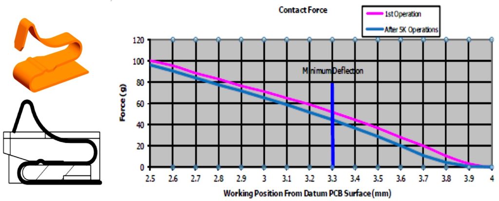 Figure 1: This gold-plated BeCu battery contact yields up to a 0.8mm deflection range while maintaining 40–100g of normal contact force.
In order to achieve optimum contact geometry, designers work through a finite element analysis (FEA) process that allows them to verify contact yield strength and graphically plot contact forces so customers can compare the data to their operational environment. Figure 1 shows a typical contact geometry and associated force deflection curve. The FEA process also reveals how the applied mating forces throughout the entire deflection range will affect contact performance, pointing out weaknesses early in the design process and allowing for critical changes before any steel is cut.
Maximizing the amount of contact deflection or the contact operating range is key to effectively absorbing tolerance mismatch or stack-up between host devices and modules. This is one of the biggest advantages of a single-piece contact system. Most modern-day medical applications utilize derivatives of the historic, single-piece battery-style connector contacts due to their proven-robust handling capabilities based on their physical size, broad deflection range, and proven normal contact force in critical applications. Additionally, as noted above, selecting gold-plated BeCu contacts will only further maximize a connector’s performance results.
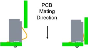 Figure 2: PCBs can be mated in the vertical direction without any damage to the contacts for error-free module insertion.
The orientation or mating direction of a connector is also critical for application success, and is based on its positioning within a device, as it must ergonomically accept the module from the user. Figure 2 shows a right-angle, cantilever beam, battery-style compression connector capable of accepting fully vertical module engagement, unlike most right-angle battery connectors, which rely on angled insertion followed by the rotational placement of the module into the device to prevent contact damage. Figure 3 highlights a connector system with a stamped contact pad. In this design, the compression contact was made to facilitate smooth module engagement and disengagement in the horizontal direction from either side. Contact geometry is extremely important in high-cycle-life applications with up to 5,000 mating cycles, as it’s a critical element in minimizing friction to reduce long-term wear at the contact interface.
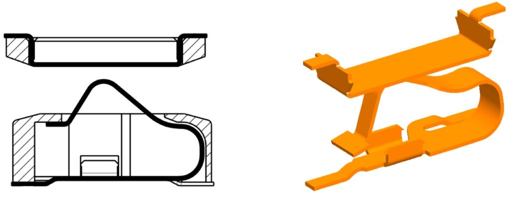 Figure 3: This bidirectional angled contact system provides smooth module engagement and disengagement from either direction.
To determine which contact system is best for a given application, simply consider the aforementioned design elements and the answers should be relatively straightforward. Understanding key application parameters, such as pitch, compressed height, and mating angle and direction will provide connector designers with enough base information to formulate a preliminary solution. Oftentimes, a preexisting contact design will meet all or most of the application requirements and create a solid foundation upon which to start a technical dialog. Further, by exchanging CAD models, both connector and product design engineers can visually determine how a connector will fit and function within a specific application, again providing the ability to make any dimensional adjustments before any steel is cut, and effectively saving time and money critical to the success of medical device developments.

Recently posted:
[related_posts limit=”10″]