Bringing Modularity to Multi‑Board Systems
Characterization and modeling of connector losses in internal connector interfaces.
Article Contributed By Baptiste Bouix, Product Manager, Würth Elektronik
When two or more PCBs need to be interconnected, designers must select the appropriate connectors for their application. However, choosing the wrong connector can compromise the entire design.
Larger pitches like 0.8 mm and 1.0 mm provide a bigger contact area, higher current-carrying capacity, and are more mechanically robust. The Würth Elektronik 1 mm BTB connectors series can be assembled with different mated heights, as well as the 0.8 mm pitch BTB connectors series which is available in different polarities.
Würth Elektronik’s WR‑BTB series of precision‑manufactured BTB connectors for high‑speed applications is distinguished by its high signal integrity. Available in various configurations, the 0.4 mm pitch series features a particularly low‑profile design, enabling it to reliably meet a wide range of requirements due to its small stacking height (0.9 mm height) allowing a very compact design.
Signal integrity testing of BTB connectors and results
To represent loss mechanisms and modeling approaches for internal connector interfaces, Würth Elektronik established a test setup. Engineers performed high‑frequency tests on both connector series using customized test fixtures. Measurements were carried out on specially developed test PCBs with 50 Ohm (100 Ohm differential) transmission lines. Calibration boards were also created to compensate for line losses and measured accordingly. The test setup utilized a Rohde & Schwarz VNA ZVB 20 vector network analyzer with a frequency range from 10 MHz to 20 GHz (Figure 1).
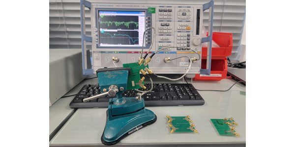
Figure 1: Test setup with calibrated test boards.
The signal characteristics described below apply to all pin positions except the outermost pins (Figure 2). It is recommended that these outer pins be assigned to low frequency signals, power rails, or ground return paths, an approach already implemented in many high-speed signaling standards.
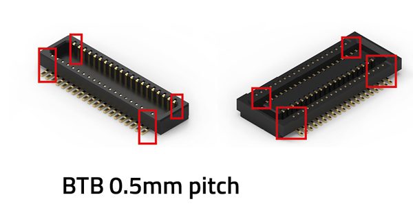
Figure 2: Outlier pins for BTB 0.5 mm connectors.
The loss models are derived from measurements that include the contribution of the test fixture in addition to the connector itself. The calibration procedure compensates for the transmission line losses of the test PCB; however, residual fixture effects at the connector interface cannot be fully de-embedded with the current two-port setup. As a result, the models intentionally represent a conservative upper bound of connector insertion loss. This approach is suitable for system-level loss budget evaluation: a design that meets its loss budget using these models will have margin in practice.
The GSG (ground–signal–ground) single-ended configuration assumes that the transmission path inside the connector consists of a signal pin (S) flanked by two ground or unrelated signal pins (G). In the GSSG (ground–signal–signal–ground) differential configuration, two adjacent pins (SS) form a differential pair, surrounded by two ground or unrelated signal pins (G).
Signal-ended and differential signaling
The insertion loss can be approximated using a conservative quadratic model. The same approach applies to measurements in a single-ended or a differential fixture:
This expression describes the insertion loss (IL) as a function of frequency f. The model intentionally overestimates the losses slightly to enable a conservative performance evaluation.
Parameter explanation [1]:
- C : constant term representing baseline DC loss, ideally near 0 dB but may include fixture offsets.
- Bf : linear term representing frequency‑dependent losses such as conductor losses and dielectric effects at low frequencies.
- Af² : quadratic term representing dielectric losses, skin‑effect‑related losses, and dispersive effects.
Variable mating height
The WR-BTB connectors series with 0.8 mm and 1.0 mm pitches can be assembled with different mated heights (Figure 3). This property allows designers to find the right mezzanine connector for their applications.((caption))
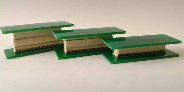
Figure 3: Variable mating height of the 1 mm pitch BTB connector series
To account for variable mating height, the coefficients A, B, and C are decomposed into two components: a baseline value at the minimum mating height and an incremental term. For both the 0.8 mm and 1.0 mm pitch series, the mating height increment is 1 mm. Accordingly, A, B, and C are expressed as functions A(n), B(n), and C(n), where n represents the number of increments from the minimum mating height, i.e., the difference between the minimum and the target mating height.
As an example, for a 5 mm minimum mating height series (WR-BTB 0.8 mm pitch):
For a mated height of 14 mm, n will be 9, so the model will be:
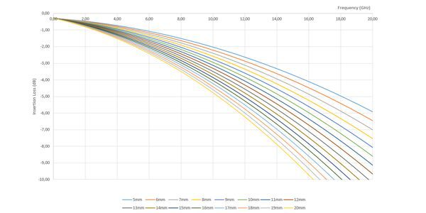
Figure 4: Attenuation curve of the BTB 0.80 mm pitch GSSG 100-ohm Insertion loss profiles, viewing all variable mating heights.
All parameter values for BTB 0.8 mm and 1 mm pitch variable mating height can be found in the series datasheet.
Compatibility with digital signal chains
While these models can be used to assess distortion in analog signals, they are most effective for evaluating connector compatibility with digital signaling, both single-ended and differential. Board-to-board applications span a wide range of protocols and interface standards. The following tables provides guidance on the expected performance of Würth Elektronik board-to-board connector systems and is not intended to replace proper compliance checks or full signal chain evaluation.
As a general guideline, connector series are ranked from lowest to highest high-speed signal integrity performance. Given sufficient pin count, higher-performing series can replace lower-tier options. The compatibility assessments presented here are based solely on insertion loss models. Return loss and crosstalk (NEXT/FEXT) are not included in this revision and should be independently evaluated, particularly for noise-sensitive or crosstalk-limited interfaces (e.g., parallel buses)
| WR-BTB 0.8 mm and 1.0 mm Pitch (High Mating Heights) | ||
| Interface Category | Supported Standards / Use Cases | Notes |
| PCI Express | PCIe Gen2; Gen3 (conditionally) | Gen3 possible with reduced system loss budget |
| USB | USB High-Speed Inter-Chip; USB SuperSpeed up to USB 3.2 Gen1 | Suitable for typical embedded interconnects |
| Ethernet | XAUI (10 Gigabit Ethernet MII) | High-speed differential signaling supported |
| Display & Camera | Serial and parallel interfaces | Covers common internal video/data links |
| Internal Buses | SPI, I²C, parallel buses | Suitable for control and low-speed data |
| WR-BTB 0.8 mm and 1.0 mm Pitch (Low Mating Heights) | ||
| Interface Category | Supported Standards / Use Cases | Notes |
| PCI Express | PCIe Gen3; Gen4 (conditionally) | Gen4 possible with reduced system loss budget |
| USB | USB High-Speed Inter-Chip; USB SuperSpeed up to USB 3.2 Gen2 | Higher data rates supported vs. high mating height |
| Ethernet | XFI / SFI | Suitable for 10G serial interfaces |
| MIPI Interfaces | MIPI D-PHY (CSI / DSI) | Supports high-speed camera and display links |
| Previously Listed | All interfaces from high mating height category | Full backward compatibility assumed |
| WR-BTB 0.4 mm Pitch | ||
| Interface Category | Supported Standards / Use Cases | Notes |
| PCI Express | PCIe Gen4; Gen5 (conditionally) | Gen5 possible with reduced system loss budget |
| USB | USB High-Speed Inter-Chip; USB SuperSpeed up to USB 3.2 Gen2 | Equivalent USB capability as 0.8/1.0 mm low mating height |
| MIPI Interfaces | MIPI M-PHY (CSI / DSI) | Supports very high-speed serial interfaces |
| MIPI Interfaces | MIPI D-PHY (CSI / DSI) | Widely used for camera/display applications |
| Previously Listed | All interfaces from prior categories | Full backward compatibility assumed |
| WR-BTB 0.5 mm Pitch | ||
| Interface Category | Supported Standards / Use Cases | Notes |
| DDR Memory | DDR4 SDRAM | Insertion loss budget met; requires additional NEXT/FEXT validation for parallel bus operation |
| Ethernet | 25GBASE-KR | High-speed backplane/board-level interface |
| Previously Listed | All interfaces from prior categories | Full backward compatibility assumed |
BTB connectors are available in numerous shapes, sizes, and configurations, allowing designers to reliably interconnect PCBs in a wide range of applications.

Baptiste Bouix
Product Manager Specialist Data Transmission at Würth Elektronik (All pictures: Würth Elektronik)
[1] All parameter values for BTB 0.4 mm and 0.5 mm pitch can be found in the series datasheet.
Würth Elektronik offers BTB connectors with following pitches:
- WR-BTB 0.4 mm pitch High-Speed Low-Profile connectors series
- WR-BTB 0.5 mm pitch High-Speed connectors series
- WR-BTB 0.8 mm pitch Variable Mating Height connectors series
- WR-BTB 1.0 mm pitch Variable Mating Height connectors series
Visit Würth Elektronik to learn more.
Like this article? Check out our other Test and Measurement articles, our Datacom Market Page, and our 2026 Article Archive.
Subscribe to our weekly e-newsletters, follow us on LinkedIn, Twitter, and Facebook, and check out our eBook archives for more applicable, expert-informed connectivity content.
- Bringing Modularity to Multi‑Board Systems - June 30, 2026
- Engineering’s Future is AI-Inspired, Human-Led - June 23, 2026
- How High-Reliability Connectors Meet the Demands of Satellite Engineering - June 23, 2026