What is a TNC Connector?
Meet the Connector: TNC Connectors
A threaded variant of the BNC, this RF connector is favored for applications in which vibration or shock is present.
TNC connectors are a threaded version of the popular BNC, a circular radio frequency connector used to connect RF cables and devices. Its 7/16″-28 threads can be tightened to reinforce the connection, making it suitable for use in high-vibration and high-stress environments such as military applications, Test & Measurement systems, communication infrastructure, and industrial RF installations. The interface specifications are referenced in MIL-STD-348.
“The TNC provides a better connection than its BNC counterpart providing a higher performance and works up to 11GHz compared to 4GHz for standard BNC connectors. The threaded coupling also makes the TNC more water and dust resistant than BNC and many are available in IP67 or IP68 ratings for use in outdoor applications,” said Brian Tea, COAX Connectors.
The TNC connector was invented in the 1950s at Amphenol by Paul Neill and Carl Concelman to provide more secure alternative to the BNC. There are several theories behind the name TNC (and BNC before it). To some, it stands for Threaded Neill-Concelman, to honor Neill and Concelman. However, they did not invent the BNC, although Neill did develop the N connector, and the smaller type BN is called a Baby Neill by the U.S. Navy.
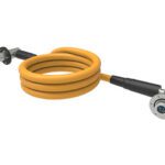
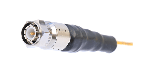
TNC Reverse Polarity IP68 Mated Crimp / Crimp Plug from COAX Connectors. 14-045-B3-DA is a straight crimp reverse polarity TNC plug with an IP68 rating with a white bronze plated body for use in outdoor antenna applications.
Configurations
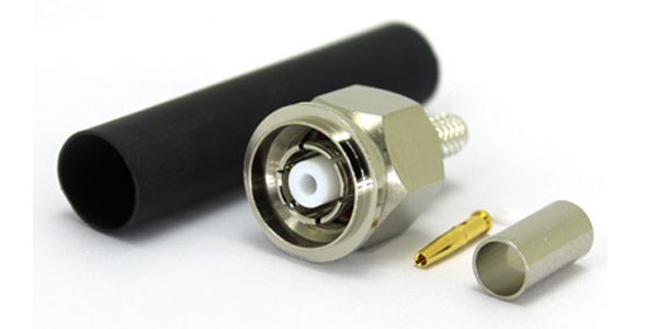
Plug Types (Male): The TNC plug features a center pin (male contact) surrounded by an outer coupling nut with internal threads. Standard plug configurations include straight (inline) and right-angle variants. The right-angle plug routes the cable perpendicular to the mating axis, useful in space-constrained installations. Reverse-polarity (RP-TNC) plugs swap the gender of the center contact, placing a female socket in the plug body. This configuration is common in consumer Wi-Fi equipment to prevent non-certified antenna connections.
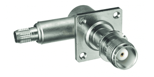
Receptacle Types (Female): TNC receptacles (jacks) present a female center contact (socket) and a threaded outer barrel. They are available as panel-mount, bulkhead, PCB edge-mount, and surface-mount variants. Bulkhead receptacles include a jam nut or flange for chassis mounting. PCB versions use through-hole or SMD termination for direct board integration.
Materials
The connector body is typically made of brass with nickel, silver, or gold plating to enhance corrosion resistance and reduce contact resistance. Center contacts are commonly made from beryllium copper or brass, gold-plated to ensure reliable low-resistance mating and longevity through repeated mate/unmate cycles. The dielectric insulator separating the center conductor from the outer body is fabricated from PTFE (polytetrafluoroethylene), chosen for its low dielectric loss, dimensional stability across temperature extremes, and chemical inertness.
Radiall’s TNC self-lock was designed in 2011 for airborne systems. The range includes cable plugs operating in the range DC-18 GHz/50 ohms.
Sealing Technology
TNC connectors are available in both standard and hermetic/weatherproof versions. Environmental sealing is achieved through captive O-rings seated in grooves on the mating interface, compressing upon full thread engagement to create an IP67-rated barrier against moisture and dust ingress. Some military-grade variants incorporate fluorosilicone or Buna-N O-rings for resistance to fuels and hydraulic fluids. Hermetically sealed versions use glass-to-metal seals at the center conductor feedthrough, providing a hermetic barrier suitable for pressurized or vacuum enclosures.
Technical Features
The TNC connector operates reliably from DC to 11 GHz, with precision-grade versions extending performance to 18 GHz. Its characteristic impedance is 50 Ω (75 Ω versions exist for video applications). The threaded coupling mechanism — typically a 7/16–28 UNEF thread — provides a secure, vibration-resistant connection. Maximum VSWR is typically ≤1.3:1 across the rated frequency range, with minimum RF leakage due to the fully shielded, continuous outer conductor design. Mating durability is rated at a minimum of 500 engagement cycles; ruggedized variants exceed that rating significantly.
Winchester Interconnect’s TNC and TNCA series threaded coaxial RF connectors deliver exceptional performance at higher frequencies, typically up to 11 GHz (with precision versions reaching 18 GHz), and in applications subject to high vibration or shock.
Winchester Interconnect’s TNC and TNCA series threaded coaxial RF connectors deliver exceptional performance at higher frequencies, typically up to 11 GHz (with precision versions reaching 18 GHz), and in applications subject to high vibration or shock.
Markets and Applications
Military and Aerospace, Telecommunications and Wireless Infrastructure, Test & Measurement, Transportation, Automotive, Industrial, Medical
The TNC connector is more robust than the BNC and more compact than the N-type, making it one of the most broadly deployed RF connector families across both commercial and military applications.
Suppliers
COAX Connectors, Molex, Radiall, Rosenberger, TE Connectivity, Times Microwave Systems, Winchester Interconnect
Connector Configuration
| Plug Types | Straight (inline), Right-Angle, Reverse-Polarity (RP-TNC), Bulkhead Plug, PCB Mount Plug |
| Receptacle Mounting Styles | Panel/Bulkhead (flange or jam nut), PCB Through-Hole, PCB Surface Mount (SMD), Edge Mount, Box Mount |
| Mating Cycles (rated) | 500 minimum (standard); 1,000+ for ruggedized/military-grade variants |
| Locking Mechanism | Threaded coupling nut (positive locking via full thread engagement) |
| Thread | 7/16-28 UNEF (Unified Extra Fine) |
| Keying / Anti-Mismating | No native keying on standard TNC; Reverse-Polarity (RP-TNC) center contact gender swap serves as a physical mismating deterrent; some mil-spec variants incorporate keyed interfaces |
| Weight | Approximately 5-10 g depending on body style, cable size, and material finish |
Contact Specifications
| Contact Count | 2 (1 center conductor + 1 outer conductor/shield) |
| Contact Sizes / AWG | Center contact sized to accommodate RG-58 (AWG 20), RG-142 (AWG 18), RG-213 (AWG 13), and other common coaxial cable series; specific AWG compatibility varies by crimp or clamp configuration |
| Contact Pitch | N/A — single coaxial contact pair; no multi-contact pitch applicable |
| Contact Material | Center contact: Beryllium copper or brass; Outer contact/body: Brass |
| Contact Plating | Gold (Au) over nickel standard for center contact; Nickel or silver plating common on outer body; Gold plating thickness typically 0.75-1.27 um (30-50 uin) |
| Contact Gender | Standard TNC — Plug: male center pin, female outer shell; Receptacle: female center socket, male outer shell. RP-TNC — Plug: female center socket; Receptacle: male center pin |
| Termination Method | Crimp, solder (cup or turret), clamp (rear-release), and PCB solder pin; crimp most common for cable-mount applications |
| Contact Resistance | Center contact: <= 3 mOhm; Outer contact: <= 2 mOhm (per MIL-STD or manufacturer spec) |
| Current Rating per Contact | Typically 1-3 A continuous on center conductor (frequency and application dependent) |
| Voltage Rating | 500 V RMS (standard); up to 1,000 V RMS for high-voltage variants |
| Dielectric Withstanding Voltage | 1,000-1,500 V RMS (tested per MIL-STD-202 or IEC 60169) |
| Insulation Resistance | >= 5,000 MOhm at 500 V DC (minimum); typically >= 10,000 MOhm under standard conditions |
| Special Contact Types | Hermetically sealed center contacts (glass-to-metal seal); captive contact designs for blind-mate applications; silver-plated contacts for cryogenic or high-power RF use |
Environmental & Mechanical Performance
| IP Rating | IP67 (standard environmental versions); IP68 for submersible/mil-spec variants |
| Sealing Type | Interface O-ring seal (mating face); cable entry grommet or boot seal; hermetic glass-to-metal seal on sealed feedthrough variants |
| Seal Material | Buna-N (Nitrile) — general purpose; Fluorosilicone (FVMQ) — fuel/solvent resistance; EPDM — weathering/ozone resistance; PTFE — chemical inertness; Silicone — wide temperature range |
| Operating Pressure | Typically rated to 1 atm differential (standard); up to 3-5 atm for ruggedized/subsea variants |
| Proof Pressure | 1.5x operating pressure (per MIL-STD testing); typically 15-75 psi proof pressure depending on variant |
| Immersion Depth Rating | IP67: 1 m for 30 minutes; IP68: up to 10 m continuous (variant dependent) |
| Operating Temperature Range | -65 deg C to +165 deg C (standard mil-spec per MIL-PRF-39012); -40 deg C to +85 deg C for commercial grades |
| Storage Temperature Range | -65 deg C to +200 deg C (mil-spec); -55 deg C to +125 deg C (commercial) |
| Humidity Resistance | Tested to 95-98% RH at 40 deg C for 96 hours minimum (per MIL-STD-202 Method 103); no degradation of insulation resistance or contact performance |
| Vibration Resistance | 10-2,000 Hz, 15-20 g peak acceleration (per MIL-STD-202 Method 204); threaded coupling provides inherent vibration lock superior to bayonet-style connectors |
| Shock Resistance | 50-100 g, 11 ms half-sine pulse (per MIL-STD-202 Method 213); ruggedized variants rated to 500 g sawtooth |
| Corrosion Resistance | 48-500 hours salt fog exposure (per MIL-STD-202 Method 101 / ASTM B117); nickel and gold plating provide primary corrosion barrier |
| EMI/RFI Shielding | 360 deg continuous outer conductor provides inherent coaxial shielding; shielding effectiveness typically >90 dB across operating frequency range |
| Ruggedization Level | Commercial, Industrial, and MIL-SPEC (MIL-PRF-39012 / MIL-DTL-55339) grades available; MIL-spec versions meet stringent environmental, mechanical, and electrical requirements for airborne, shipboard, and ground military platforms |
Insulator & Overmold Materials
| Plug Insulator Material | PTFE — standard dielectric insulator in virtually all TNC plug configurations, both commercial and MIL-PRF-39012 mil-spec; chosen for low dielectric loss (tan delta < 0.0002) and stability across the full -65 deg C to +165 deg C operating range |
| Receptacle Insulator Material | PTFE — used in panel-mount, bulkhead, and PCB-mount TNC receptacles; Glass-to-metal (ceramic/glass bead) seal — used in hermetically sealed TNC feedthrough receptacles for pressurized enclosures, avionics, and vacuum applications |
| Overmold / Backshell Material | TNC cable assemblies most commonly terminate without an overmold on the connector body itself, as the machined brass coupling nut provides inherent mechanical protection; where strain relief is applied: heat-shrink adhesive-lined polyolefin tubing is the most common field solution; polyurethane overmold is used on pre-made commercial assemblies for environmental sealing at the cable entry; aluminum alloy backshells are used on mil-spec TNC assemblies (e.g., MIL-DTL-55339) requiring EMI continuity and robust cable strain relief |
Compliance, Electrical Performance & Qualification
| RoHS / REACH Compliance | RoHS 3 (EU Directive 2015/863) compliant on commercial and most current mil-spec variants; REACH SVHC compliance declared by major manufacturers; exemptions may apply to specific military/aerospace variants with legacy finishes |
| Halogen Free | Standard TNC connectors are not inherently halogen-free due to PTFE insulator (fluoropolymer); halogen-free variants available on request using alternative dielectrics; PTFE is generally considered low-risk despite fluorine content as it is chemically inert and non-bioavailable |
| UL Flammability Rating | PTFE insulator: UL 94 V-0 (self-extinguishing); connector body materials (brass, nickel-plated) are non-combustible; overmold/backshell materials rated UL 94 V-0 or V-2 depending on polymer selection |
| Impedance | 50 Ohm (standard); 75 Ohm versions available for video/CATV applications |
| VSWR | <= 1.3:1 at 0-11 GHz (standard); <= 1.15:1 for precision/low-reflection variants up to 18 GHz |
| Insertion Loss | <= 0.1 dB at 1 GHz; <= 0.3 dB at 11 GHz (typical per mated pair) |
| Data Rate / Bandwidth | DC to 11 GHz (standard commercial); DC to 18 GHz (precision grade); supports broadband RF, microwave, and high-speed digital signal transmission |
| EMI Filter Integrated | Not standard; TNC is a passive RF connector; filtered TNC variants (with integrated capacitive or LC filter elements) are available from specialist manufacturers for EMI suppression at feedthrough points |
| Qualification Test Standard | MIL-PRF-39012 (primary mil-spec for RF coaxial connectors); MIL-DTL-55339; IEC 60169-17 (international standard for TNC connectors); IEEE 287 for precision RF connector performance |
| Shock Test Standard | MIL-STD-202 Method 213; MIL-STD-810 Method 516 for platform-level shock qualification |
| Vibration Test Standard | MIL-STD-202 Method 204; MIL-STD-810 Method 514 for platform-level vibration qualification |
| Thermal Cycling Test | MIL-STD-202 Method 107 (-65 deg C to +165 deg C); IEC 60068-2-14; typically 10-100 cycles depending on qualification level |
| HALT / HASS Tested | Not universally required by standard TNC specifications; HALT and HASS applied by manufacturers of ruggedized/aerospace variants to validate design margins beyond standard qualification |
| Space Qualification | Select TNC variants qualified to NASA and ESA standards; must meet MIL-PRF-39012 as baseline plus additional screening for outgassing, radiation tolerance, and thermal vacuum performance |
| Outgassing (space) | PTFE insulator: inherently low outgassing; space-qualified TNC assemblies must meet NASA ASTM E595 outgassing requirements: Total Mass Loss (TML) <= 1.0%, Collected Volatile Condensable Materials (CVCM) <= 0.1%; adhesives, overmolds, and lubricants are primary outgassing concerns and must be individually screened |
Like this article? Check out our other Meet the Connector and Connector Basics articles, our Sensors and Antennas Market Page, and our 2025 and 2026 Article Archives.
Subscribe to our weekly e-newsletters, follow us on LinkedIn, Twitter, and Facebook, and check out our eBook archives for more applicable, expert-informed connectivity content.
- EU Battery Regulation Prompts Design Changes for Battery Connectors - July 14, 2026
- What is an LGA Socket? - June 30, 2026
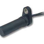
- What is a Speed Sensor? - June 23, 2026