Meet the Cable — NDT Cables
NDT cable is a shielded coaxial or multiconductor cable assembly that connects ultrasonic, eddy current, and phased array probes to non-destructive testing (NDT) instruments, carrying high-voltage excitation pulses to the probe and returning low-level echo or impedance signals to the receiver. It is built to stay flexible and electrically quiet through constant handling, scanner motion, and exposure to couplants and oils. Inspection technicians, instrument OEMs, and automated scanner builders use it to find flaws in welds, castings, tubes, rail, and composites without damaging the part.
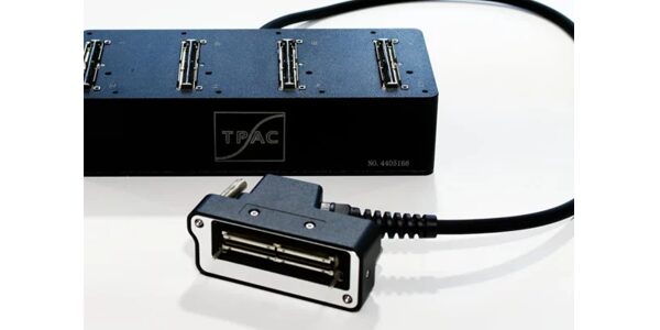
NDT setup with I-PEX connectors from the Phased Array Company
Origin & Development
NDT cable evolved alongside the probes and instruments it serves. Ultrasonic flaw detection was pioneered in the 1930s and 1940s with Floyd Firestone’s work on the supersonic reflectoscope, and eddy current testing was commercialized in the same era. Early probe leads were general-purpose coax, and the compact 50 Ω micro-coax and RG-type cables, MIL-DTL-17 types such as RG-174 and RG-316 among them, became the foundation for today’s assemblies.
There is no dedicated NDT cable standard. Cable performance is evaluated as part of the probe-and-instrument system under documents such as EN 12668 and ASTM E1065, while the underlying coax is often built to MIL-DTL-17 or an equivalent manufacturer specification. Phased array and eddy current array systems with dozens or hundreds of channels pushed the category toward bundled micro-coax and high-density multipin interconnects.
Design Highlights
Engineers choose NDT cable for signal integrity and survivability. In pulse-echo testing, a high-voltage pulse of up to several hundred volts leaves the instrument and a microvolt-to-millivolt echo returns on the same line, so the cable needs a well-controlled impedance (typically 50 Ω), tight shielding against electromagnetic interference, and low capacitance. Excess cable capacitance loads the transducer, reduces pulse amplitude, and narrows bandwidth, which hurts axial resolution. Foamed or solid PTFE dielectrics and silver-plated copper conductors and braids are premium cable options.
The main trade-offs are flexibility, loss, and size. Finer micro-coax and stranded conductors flex longer and fit smaller probes, but add attenuation and are harder to terminate. Larger coax such as RG-58-class cable has lower loss and is easier to terminate, but is stiffer and heavier at the probe. Jacket choice matters just as much as electrical design: polyurethane and silicone jackets resist abrasion, oils, and couplant, while PTFE tolerates high temperature. In practice the most common field failure is mechanical, a broken conductor or shield at the probe-end strain relief, so flex-rated stranding and good strain relief often matter more than raw electrical specifications.
Looking ahead, rising channel counts for phased array, full matrix capture, and total focusing method inspection are driving denser multi-coax bundles, smaller connectors, and thinner, more flexible jackets. Robotics and automation expansion is also raising demand for high-flex cable with long cycle life.
Connectorization
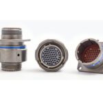
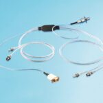
NDT cables are most often supplied as factory-terminated assemblies, with custom lengths and connector combinations typical. The probe end is usually a small, locking, push-pull or threaded connector, with Lemo 00 and 01, Microdot (10-32 UNF), and SMA common on probes, and BNC or Lemo at the instrument end. Phased array and array eddy current probes use multi-contact connectors, often proprietary or high-density types, with each channel terminated to its own micro-coax contact.
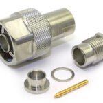
Termination is typically crimp or solder, and many small coax connectors use a center contact, a crimped or soldered shield ferrule, and a cable-specific collet or clamp. Precise stripping dimensions and the correct crimp tool and die are required, so assemblies built in the field without them are a frequent source of intermittent faults.
Common pitfalls include choosing a connector whose cable code does not match the cable’s outer diameter or dielectric, mixing 50 Ω and 75 Ω BNC parts, poor shield termination that adds noise, and confusing similar-looking Lemo 00, Lemo 01, and Microdot connectors, which are not interchangeable. Because most failures occur near the probe, correct strain relief and bend radius at the connector are essential.
Markets & Applications
Oil & gas, power generation (including nuclear and boiler inspection), military and aerospace, transportation, automotive, manufacturing, and infrastructure.
Market-specific variants include high-temperature PTFE-jacketed leads for hot surfaces, hardened polyurethane or armored jackets for field and oilfield use, waterproof or submersible assemblies for immersion testing, and multi-coax bundles for phased array.
Technical Specifications
| Values vary by manufacturer and construction. Common ranges for coax-based assemblies are listed below. Always consult the manufacturer datasheet for current and complete specifications. | |
| IDENTIFICATION | |
| Cable Type | NDT probe cable (ultrasonic, eddy current, and phased array probe cable assemblies) |
| Standard(s) | No dedicated cable standard; coax commonly built to MIL-DTL-17 (e.g., RG-174, RG-316) or manufacturer specifications; system-level references include EN 12668 and ASTM E1065 |
| Category | Coaxial; micro-coax bundles; shielded multiconductor / twisted pair (eddy current) |
| CONSTRUCTION | |
| Number of Conductors | 1 (single coax); 2 or more (eddy current, differential); dozens to 100+ coax channels (phased array bundles) |
| Conductor Material | Silver-plated copper; tinned copper; copper-clad steel (cost-focused types) |
| Conductor Gauge / AWG | Typically 26 AWG to 36+ AWG (micro-coax); varies by cable |
| Conductor Stranding | Solid or 7-strand typical; fine-strand and flex-rated stranding for high-flex types |
| Insulation Material | PTFE (solid or foamed); FEP; polyethylene; PVC for lower-cost types |
| Shield Type(s) | Braid (commonly 90% or greater); foil + braid; served shield for flex applications |
| Shield Material | Silver-plated copper braid; tinned copper braid |
| Jacket Material | Polyurethane; PVC; FEP/PTFE; silicone |
| Overall Diameter (OD) | Approx. 0.5 mm to 3 mm for single coax (e.g., approx. 2.5 mm RG-316; approx. 2.8 mm RG-174); larger for bundles |
| ELECTRICAL PERFORMANCE | |
| Impedance | 50 Ω nominal for most ultrasonic probe cables; other values for eddy current and special designs |
| Data Rate / Bandwidth | Signal frequencies typically 0.5 to 25 MHz (up to 50+ MHz for high-resolution probes); coax itself usable well beyond |
| Voltage Rating | Typically several hundred to 1,500 V rms dielectric withstand depending on construction; confirm against pulser peak voltage |
| Current Rating | Not applicable (signal cable) |
| ENVIRONMENTAL | |
| Operating Temperature Range | Roughly −40 °C to +85 °C for PVC/PU types; up to +200 °C for PTFE types; note flex rating at temperature extremes |
| Flame Rating | Varies; PTFE inherently flame resistant; PVC and PU types often not rated; consult datasheet |
| MATERIALS & COMPLIANCE | |
| RoHS / REACH | Generally compliant; confirm per manufacturer and part number |
| Halogen Free | Typically No (PVC and fluoropolymer constructions); halogen-free jackets available on request |
| CONNECTORIZATION | |
| Compatible Connector Families | Lemo 00 / 01; Microdot 10-32; BNC; SMA; UHF (legacy); proprietary multipin for phased array and array eddy current |
| Termination Methods | Crimp; solder; factory-assembled (most common) |
| Contact / Pin Size Match | Connector-specific; select the connector cable code that matches cable OD and dielectric |
| Tooling | Connector-specific crimp tool and die set; coax stripping tool for correct strip dimensions |
Suppliers
Aptiv (formerly Winchester), I-PEX, TE Connectivity, Teledyne Reynolds Times Microwave Systems, Cinch Connectivity Solutions, Smiths Interconnect, Trexon, IMS, L-Com
Distributors
CDM, DigiKey, Heilind Electronics, ICC (Interstate Connecting Components), Kensington Electronics, Mouser, PEI Genesis, Sager Electronics, TTI Inc.
Related Products
Like this article? Check out our other Meet the Connector and Connector Basics articles, our Military and Aerospace Market Page, and our 2025 and 2026 Article Archives.
Subscribe to our weekly e-newsletters, follow us on LinkedIn, Twitter, and Facebook, and check out our eBook archives for more applicable, expert-informed connectivity content.

- Meet the Cable — NDT Cables - October 27, 2026
- How We’re Creating Connections for Life - October 16, 2026
- DuraClik Connectors: Beyond the Garage - October 16, 2026