How to Design Optical Fiber Cables for Interconnect Solutions in Harsh Environments
For harsh environments, such as avionics and defense, key issues related to high temperatures, vibration, and shock must be considered to maximize the efficiency of optical technologies.

For two decades, the need for ever-increasing capacity and speed to move data through our electronic devices has generated the deployment of millions of kilometers of optical fiber across the planet, thus enabling the creation of very high-speed networks. In telecommunications, the advantages linked to fiber optics, including high data rate and reliable transmission (EMI protection), have been known to engineers for a very long time. Today we consider technologies related to photonics to have reached maturity. However, for harsh environments, such as avionics and defense, key issues related to high temperatures, vibration, and shock must be considered to maximize the efficiency of optical technologies. In space, requirements are even more critical, as the photonic payload must also resist radiation, atomic oxygen, and outgassing.
Used in communication systems, navigation, sensing, and weapon systems, optical fiber technology is designed for:
- Data transmission with high data rate up to 40 Gb/s
- Optoelectronics devices such as transceivers for optical-to-electrical conversion
- Modulation of a radio frequency signal and transmission over optical fiber (RF over fiber)
- Power supply through a fiber optical cable (Power over fiber)
- Optical sensor with optical fiber cable for sensing technology
Standard optical fiber cables can be used in internet networks for everyday applications, but the harsh environments of avionics and space require fiber optics with optimized design and materials.
Optical fiber cables compatible with rugged connectors
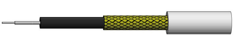
Commonly, optical fiber cable structure is defined as pictured below.
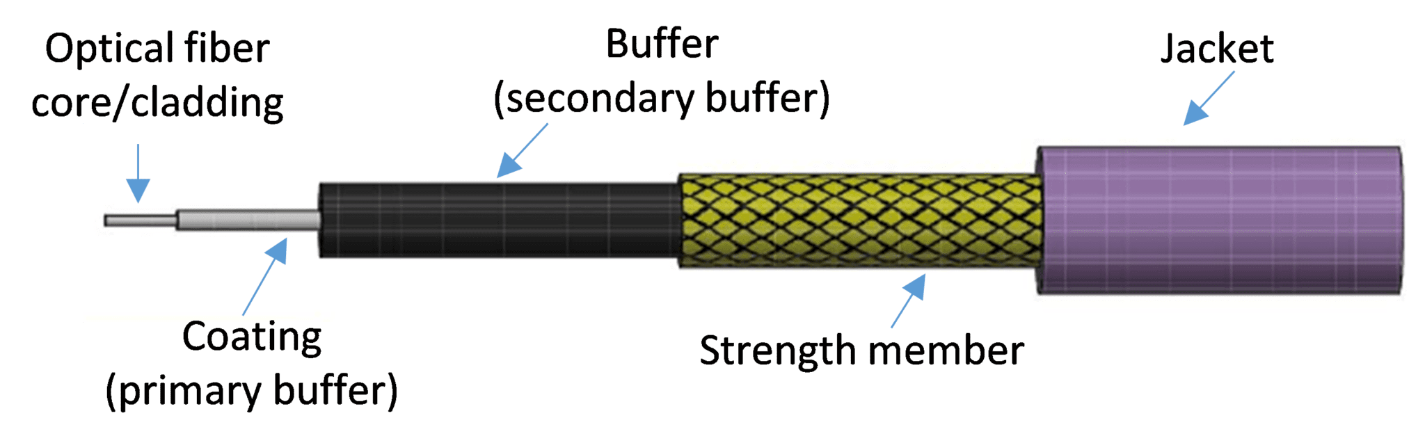
Several layers of protection surround a typical Axon’ optical fiber cable.
For harsh environments, however, materials that comprise an optical fiber cable can be optimized as follows:
- An optical fiber core/cladding in silica
- A coating (also called the primary buffer) in various materials such as polyacrylate, polyimide, and silicone
- A buffer (also called the secondary buffer) in various materials such as fluoropolymers (ETFE, PTFE, PFA, and FEP)
- A strength member in aramid yarn or glass fiber
- An external jacket in various materials such as fluoropolymers (ETFE, PTFE, PFA, and FEP)
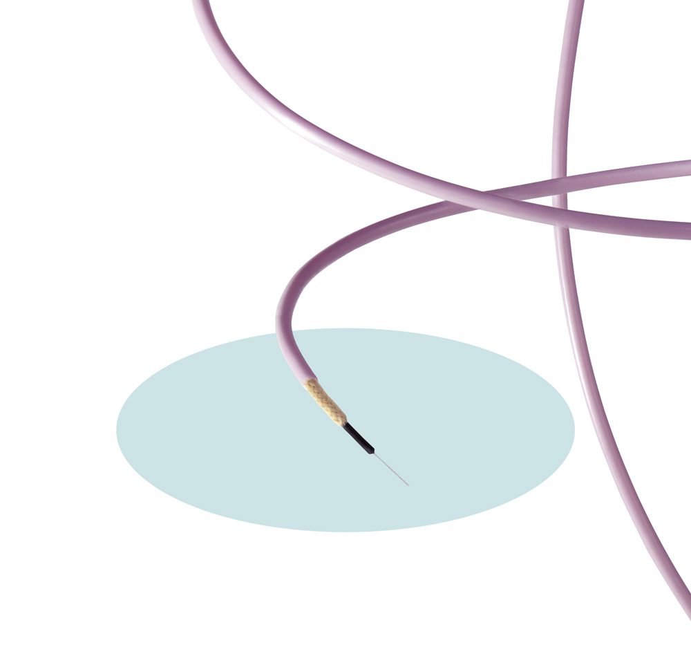
Axon’ optical fiber cable is designed to resist harsh environments.
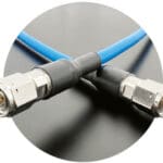
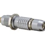
Optical fiber cables must be fully compatible with a wide range of standardized contacts or connectors including ARINC 801, MIL (e.g., MIL-PRF-29504), and ST, FC, and LC connectors. They also must endure operational constraints (stripping, shrinkage, crushing) and resist harsh environment conditions (temperature extremes, contaminant exposure, and radiation).
Reliable stripping for high quality optical fiber links
When assembling optical cables to connectors, the cable surface must remain clean at each stage of the process. During connector assembly, the glue must adhere to the entire surface to assure an effective retention of the connector-cable couple. Stripping plays a key role in the assembly process of connectors. This is particularly true for manual and automatic stripping of buffer and jacket, which must be reliable.
As far as the buffer is concerned, stripping low-density extruded PTFE is a delicate operation because it can lead to the formation of filaments. Stripping silicone is also a key issue because the operation can bring dust particles to the cable surface. To avoid this problem, choose extruded ETFE as the buffer material to provide very clean cut and cable surfaces. ETFE material is chosen for the external jacket for the same reason.
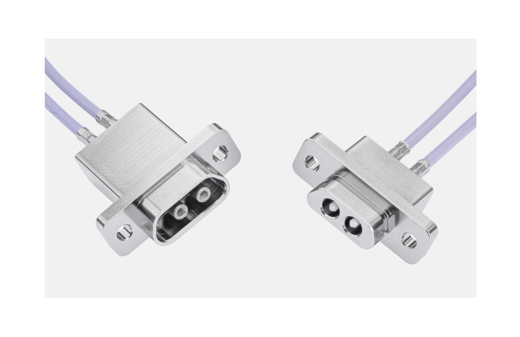
Axon’ optical fiber cables terminated with Axon’ micro-D based optical connectors.
Why a cable with low shrinkage is important
The connection area between the connector and the fiber optic cable is a sensitive area, which if not made reliable, can cause degradation of the optical attenuation and breakage of the fiber. The optical fiber must be fully fixed to the connector to absorb severe constraints such as temperature changes and vibrations.
To secure the area of connection, the process method begins by choosing a cable with very low shrinkage. The minimum shrinkage or elongation value defined in the ARINC 802 standard is 15 mm. But for harsh environments, some studies have shown that having a value down to 0.5 mm sample of 3.5 m length will be much more efficient.
Limiting shrinkage/elongation also avoids the cost and the time-consuming process of thermal pre-conditioning, which benefits industrial manufacturing.
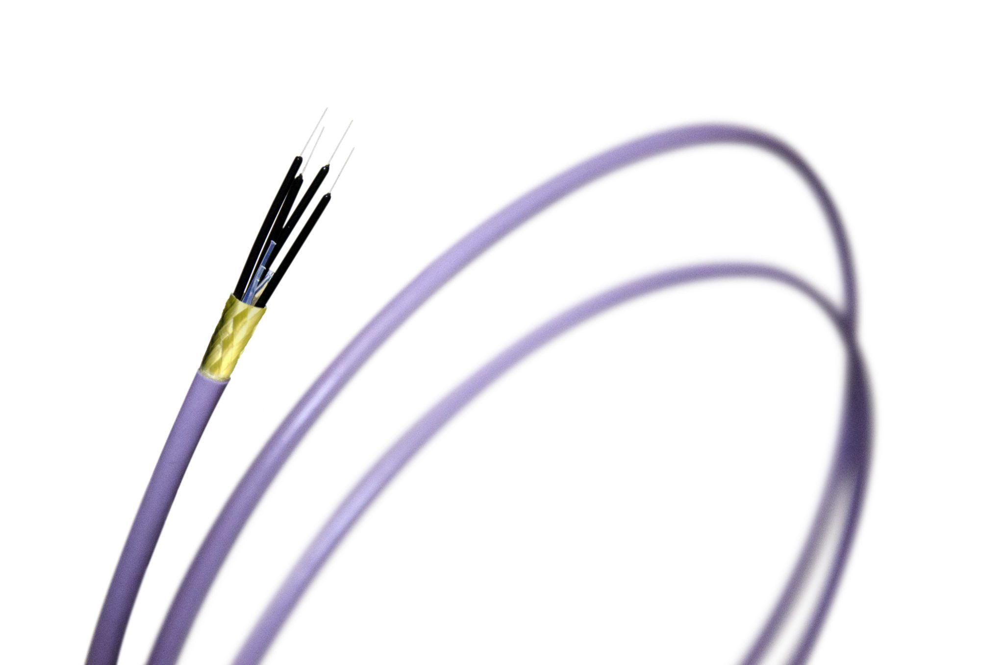
Example of 4-way fiber optic cable made by Axon’. Axon’ optical cables can be used without any pre-processing, whereas some competitor optical fiber cables need a thermal cycling of a few days before using.
Mechanical resistance
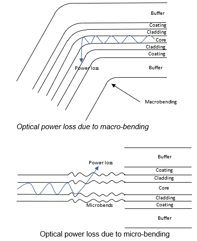
During the integration and routing phases in the equipment, the cables can be subjected to numerous constraints such as crushing, bending, torsion, shock, or kink. Beyond the installation recommendations, it is therefore very important to preserve not only the mechanical integrity (resistance of the structure) but also the optical performance of the cable. Attenuation should not be excessively increased at the wavelengths used. Micro and macro bending on an optical fiber generates leakage modes (sheath mode) and leads to an increase in attenuation performance. This is a well-known phenomenon.
These mechanical constraints will be combined with environmental constraints including temperature and vibrations, so the structure of the cable must be optimized to minimize their negative effects on optical performances. A way to improve the cable structure is to optimize the extrusion process as well as the adhesion between the different layers of materials. A good knowledge of the different materials used is a real advantage for the design. In the end, a so-called “tight” structure meets the different requirements and obtains interesting results in terms of attenuation: A substantial crushing force of 500N leads only to a residual increase in attenuation of the order of 0.05 db (fiber optic cable type OM3 and @ 850 nm).
Furthermore, some mechanical characteristics can be added such as:
- A bending radius of much less than 10 times the optical cable diameter
- A tensile strength of much more than 200 N
Radiation resistance: a key issue for space applications
In space, optical fibers are subjected to ionizing radiation that can cause damage. The high energy ions will break the chemical bonds of the glass that compose the optical fiber. Darkening of the optical fiber occurs due to micro or macro defects. However, optical fiber doped by fluorine is very resistant to radiation (at least until 200 MRad).
Another extraterrestrial threat is atomic oxygen (ATOX) which erodes and damages materials including polymer insulated wires and cables. Protective solutions are achieved by wrapping, coating, or isolating wires in aluminum trays, but these solutions add mass to the system and decrease flexibility. Lightweight fiber optical cables that can resist ATOX are a real asset in this field. For space applications, another critical feature for cable materials is low outgassing. Outgassing materials release trapped gas, which can leave residue on instruments and surfaces. To evaluate outgassing, the key material parameters are measured for total mass loss (TML) and collected volatile condensable materials (CVCM). The rate of outgassing increases at higher temperatures because the vapor pressure and the rate of chemical reaction increase.
Lightweight, flexible, and easy-to-strip fiber optics protected by Radatox, a material developed by Axon’ Cable that has a radiation resistance of at least 200 MRad (ECSS-Q-ST-70-06C). Axon’ fiber optical cables protected by Radatox are also characterized by their low outgassing in compliance with ECSS-Q-ST-70-02.
With EMI protection and a high data rate (up to 40 Gb/s), optical fiber cables have many advantages for avionics, defense, and space applications. First, they must be optimized to resist mechanical and environmental constraints linked to the application. Processing methods (including stripping, shrinkage, crushing, and radiation resistance) should also protect the integrity of the cable design. Addressing other characteristics in a design will allow these cables to operate and ensure secure links in every type of environment.
Visit Axon’ Cable to learn more.
By Emmanuel Bourelle, Product Design Engineer; Bruno Giacomini, R&D Project Manager; Stéphane Watier, International Project Manager; and Sandrine Hermant, Marketing Project Manager, Axon’ Cable
Like this article? Check out our other How to Specify articles, Mil/Aero Industry articles, and 2022 and 2023 Article Archives.
Subscribe to our weekly e-newsletters, follow us on LinkedIn, Twitter, and Facebook, and check out our eBook archives for more applicable, expert-informed connectivity content.