Connector Selection for Medical Device PCBs
When choosing a connector for a medical application, one must consider not only the typical ratings for voltage and current, but also the constraints on physical size, temperature, and durability.

Article contributed by KYOCERA AVX
Medical devices include a broad range of equipment, ranging from small implantable stimulators to room-sized MRI machines. This equipment falls under three classes based on the safety implications of possible failure modes. Class I devices present minimal potential for harm to the user and are often simple in design. 47% of medical devices fall into this class, and 95% of these are exempt from any special regulatory oversight. However, once safety concerns come into play, a device is elevated to Class II status. This class represents 43% of all medical devices and includes power wheelchairs and pregnancy test kits. Class III devices require the highest level of safety regulations and regulatory oversight. These devices sustain or support life, are implanted, or present potential unreasonable risk of illness or injury. Examples include implantable pacemakers and breast implants. Only 10% of all medical devices fall under this category.
Class I and II devices can be designed using traditional electronic components, as long as a focus is maintained on overall reliability and environmental compatibility. A wide variety of contacts and connectors are suitable for Class I and II medical applications, particularly at the PCB level for connecting wires to boards, boards to boards, and battery packs to boards.
When choosing a connector for a medical application, one must consider not only the typical ratings for voltage and current, but also the constraints on physical size, temperature, and durability. Electro-mechanical connectors make a quality connection that can replace soldering and even outperform it electrically. For medical devices, reliability is always a key factor, so connection methods are limited to insulation displacement (IDC), poke home, and traditional compression contacts.
In an IDC connector, the joining mechanism of the wire and the contact is cold welding. To achieve this phenomenon in open air, the gas between the two pieces of metal must be completely forced out. A wedge-shaped slot is forced through the insulation of a solid or multi-stranded wire in such a way as to guide the metal strands into the slot. The wedge shape exerts a tremendous force on the wire bundle, forcing all the gasses out and creating the cold weld. A simplified illustration of the mechanism is shown below. IDC connectors are easy to install, very reliable, and repeatable in a production environment.

IDC connector mating an insulated wire to a PCB
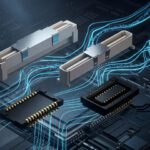
For situations when stripped wire is acceptable, the poke-home connector was introduced as a highly reliable solution for connecting a small number of discrete wires to a printed circuit board assembly. The wire is inserted into the connector and proper positioning is ensured using integrated wire guides and an end stop. Dual beam high-force contacts (typically beryllium copper) grip the exposed metal of the wire and provide an extremely low electrical resistance connection with excellent wire retention. In board-to-board applications where a large number of pins may be required, compression contacts can also be used as shown below. Two rows of contacts are situated with extremely fine pitch, as low as 0.35mm, in a low profile surface mount component. PCBs can be stacked and retained mechanically in such a way that these compression contacts create a high reliability connection to a set of exposed pads.

Poke-home connector retains and contacts at the same time
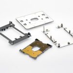
When the end goal is to create a connection between two PCBs (or a battery pack and a PCB), traditional spring force contacts can be used. To ensure reliability and environmental suitability for medical applications, special design techniques can be leveraged. For example, using gold-plated beryllium copper contacts guarantees fatigue resistance and low electrical resistance. Similarly, specialized contact shapes are used to maximize spring force, absorbing assembly tolerances while maximizing contact force even in harsh environments. An example is shown below for a surface mount connector designed for mating a battery pack to a PCB in a medical handheld product.
Compression contacts for board-to-board connector
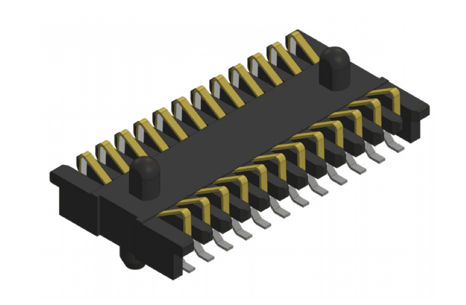
When right angle connections are required, the exact same compression spring contact mechanism can be used within the confines of a card edge connector. Shown below, the contacts are arranged vertically within a low-profile plastic housing, allowing a PCB to be inserted into the slot and contacts to be made with exposed pads on its edge. To continue reading, download this white paper in its entirety at KYOCERA AVX.
See connectors for medical devices and other applications at KYOCERA AVX.
Like this article? Check out our other High-Reliability articles, our Medical Market Page, and our 2024 and 2025 Article Archive.
Subscribe to our weekly e-newsletters, follow us on LinkedIn, Twitter, and Facebook, and check out our eBook archives for more applicable, expert-informed connectivity content.
- Bringing Modularity to Multi‑Board Systems - June 30, 2026
- Engineering’s Future is AI-Inspired, Human-Led - June 23, 2026
- How High-Reliability Connectors Meet the Demands of Satellite Engineering - June 23, 2026