Cable Backplanes Come of Age
Cable backplanes have been a longtime feature of high-performance computing, undergoing several evolutions to keep up with speed and bandwidth requirements. However, as next-generation AI computing systems take hold, the practical limits of copper have been reached, pushing connector suppliers to create products that include optical solutions.
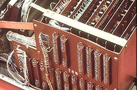
Traditional backplane and daughtercard design has been a mainstay packaging technique in large systems for many years. When early electronic systems needed more printed circuit space on which to mount discrete devices, multiple boards were typically stacked and connected using hand soldered wires, a costly solution that resulted in poor reliability.
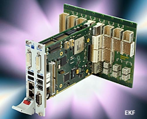
The primary function of a backplane is to provide low speed, high speed, and power interconnect to multiple daughtercards that plug into the backplane. They simplify repair and upgrade in the field by allowing replacement of a daughtercard with one that has been repaired or improved. The population of daughtercards on a backplane can be adjusted to provide performance scaling to match demand. They streamline design and manufacturing by partitioning a system into pluggable computation, storage, power distribution, and I/O modules. Modular systems that utilize industry standardized interconnects open the door to interoperable daughtercards, reducing cost and potentially introducing new competitive features.
As the number of interconnects increased, connectors mounted on the backplane expanded from simple edge card connectors to two-piece post and receptacle interfaces. The type of connector, keying, polarization, and pin configuration were often defined by specifications such as Eurocard and compact PCI to ensure mechanical and electrical compatibility. The construction of the backplane itself was upgraded by careful layout of high-speed circuits using strip line and microstrip rules to minimize impedance discontinuities. Layer counts increased into 30 or more layers while PCB materials were upgraded to improve high-speed insertion loss, return loss, and crosstalk characteristics.
As pin counts, bandwidth, and power demands increased, standard 0.1 in centerline connectors evolved in multiple ways.
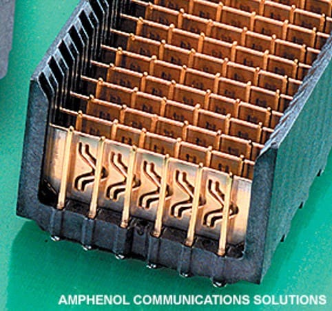
Standard grid configurations were replaced with dedicated ground pins and shields to establish controlled impedances. As differential signaling was introduced, connector contacts were arranged in shielded contact pairs to achieve higher levels of signal integrity.
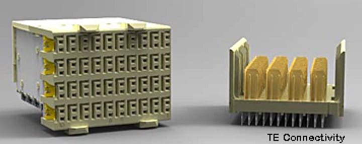
Advanced shields created virtual twinaxial contact pairs to minimize impedance discontinuities and crosstalk. Through-hole reflow soldered connectors were replaced by compliant pin press-fit termination.
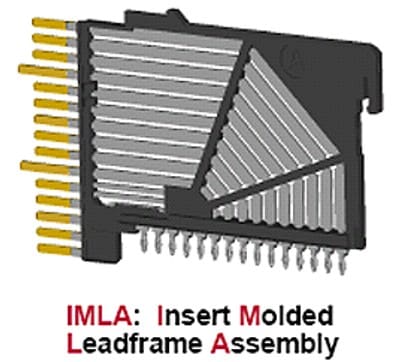
Innovative manufacturing processes were developed to increase flexibility and produce modules that minimize differences in signal delay between top and bottom row right-angle contacts.
Signal distortion due to the transition from the plated through hole on the backplane to the pin header was addressed by reducing the diameter of the hole and back drilling the hole plating to reduce electrical stubs. Some connector designs eliminated the plated through hole entirely by utilizing surface mount compressive or hot air solder reflow to pads on the surface of the backplane.
In an effort to reduce the length of copper channels in the backplane, alternative designs were introduced. Mezzanine architecture stacks PCBs and mid-plane architecture moved the backplane from the rear of the chassis to the middle of the rack with cards plugging in from both sides.
Orthogonal midplane designs eliminated the backplane entirely by allowing every daughtercard to connect directly with every other daughtercard. Orthogonal midplane design introduces some additional challenges regarding daughtercard access and cooling airflow design.

The laws of physics began to impose bandwidth and reach limitations which appear in advanced computer applications. Designers of high-speed channels found that even short PCB traces inside the box introduced unacceptable insertion loss and signal distortion while consuming increased power. This degradation of high-speed signals reduces critical channel margin and becomes a design-limiting factor in high-performance computing systems.
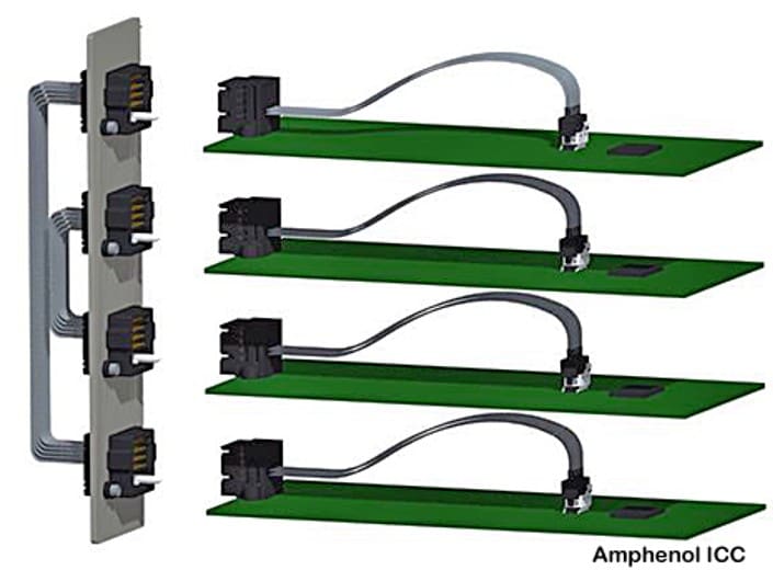
One solution is to eliminate sending high-speed signals through PCB traces and conduct them over the surface of the board via twinaxial copper cable which features much better impedance and isolation characteristics.

Cables are terminated immediately adjacent to a high-speed device, minimizing signal propagation in copper PCB conductors. The other end of the cable is typically terminated directly to an I/O connector located on the front panel. This design has proven to be highly effective for critical circuits inside the box and has been expanded to utilize both twinaxial copper and fiber optic cable.
The next logical extension of this concept is to apply this technology to replacing copper I/O channels embedded in the backplane with high-performance twinaxial cables. Low speed and power circuits continue to be supported with traditional copper backplane connectors. The decision to select a cable backplane design is driven by the IEEE 40dB insertion loss specification for high-speed Ethernet channels through PCB traces and cable.
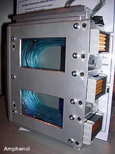
Cable backplanes have been utilized for years, primarily in advanced computers where extreme performance is the primary objective and cost is secondary. These systems utilize exceptionally large backplanes that result in long point-to-point circuits that would introduce unacceptable levels of signal loss.
Leading connector manufacturers introduced cable backplane options utilizing their highest performance backplane connectors adapted to twinaxial ribbon and discrete cable.
High-speed signals are conducted through optimized differential pair cable mounted connectors while lower speed and power circuits are handled by standard power and coaxial connectors mounted on a standard backplane. Some systems use bus bars to distribute kilowatts of power to each shelf.
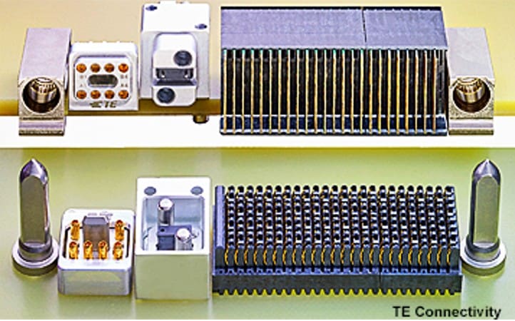
Large guideposts establish precision pre-alignment between the panel mounted cable backplane connector and mating servers.
Advanced HPC and AI server sleds may use internal over-the-board cables to provide connection between a high-speed ASIC and front panel QSFP I/O as well as connection to a back panel cable backplane.
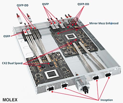
High-performance backplane connectors such as the Amphenol Paladin HD2, Molex Inception, TE Adrenaline Slingshot, and Samtec NovaRay® connectors are rated to 224G/s.
While cable backplane technology allows greater design flexibility and superior signal integrity in large systems, it also introduces its own set of challenges.
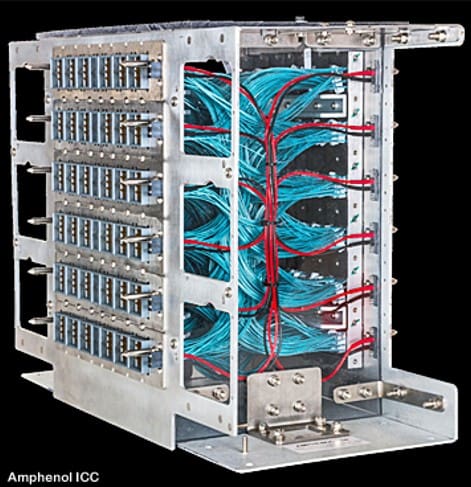
Early cable backplanes systems consisted of masses of twinaxial cables that solved the performance problem but presented manufacturing, repair, and cable management nightmares.
Some smaller cable backplanes consist of point-to-point collections of discrete twinaxial cables. Finding and repairing a single failure in the field can be difficult for a local service technician.
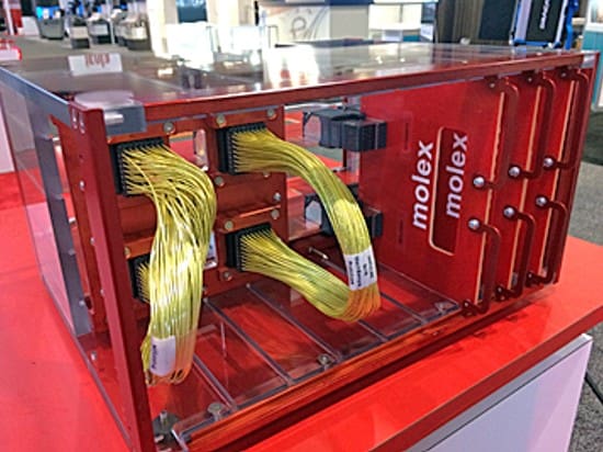
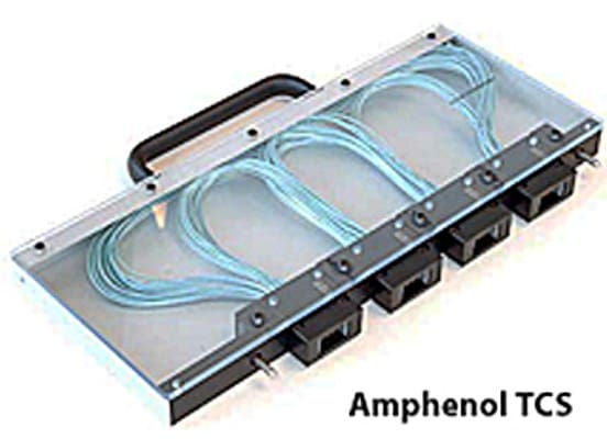
Part of the solution was to organize cables into a modular assembly that could be removed and replaced if a failure were to occur.
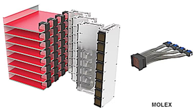
Rather than a single large assembly, the concept of modular cassettes has emerged. Several cassette concepts have evolved to address scalability and servicing issues.
Large cassettes can be bulky and add significant weight, making a robust guidance system — including generous float between mating connectors — essential. Rack tolerances must also be tightened.
Cable backplane cassettes continue to adapt to the application specific requirements of individual customers.
The issue of repair in the field has no simple solution other than to send the defective cassette back to the factory for repair.
Manufacturers of cable backplane assemblies submit their assemblies to a rigorous 100% testing regimen prior to shipment to minimize this concern. These assemblies are designed in close collaboration with their supplier. This requires access to advanced signal integrity analysis equipment and extensive experienced engineering resources, at the factory as well as through global field support.
Because of the unique electrical and mechanical requirements of high-performance computing systems, cable backplanes are custom assemblies. The connectors may be second sourced, but the final assembly is very customer specific.

TE Connectivity recently exhibited an example of a cassette cable backplane assembly that is installed in the back of a large server or switch rack.
The market for cable backplanes remains limited to high-performance systems but is growing due to the enormous demands of AI and HPC computer clusters that operate at 112G, 224G, and beyond.
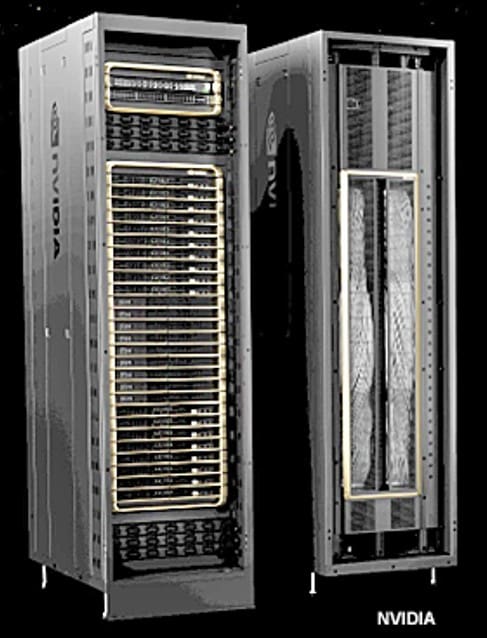
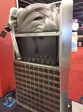
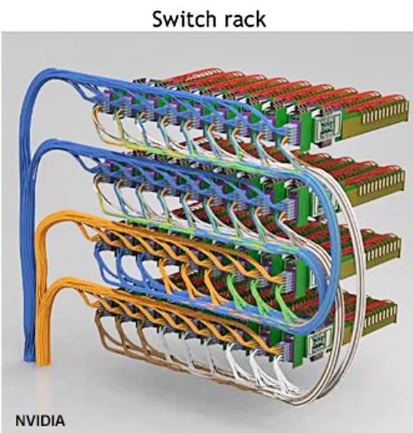
Apparently, Nvidia’s engineers did not even consider the use of a traditional PCB backplane with their new DGX GB200 NVL72 AI rack computer. The NV switch chip at the heart of this system has 50 billion transistors creating demand for
unprecedented connectivity within the rack. The solution was the use of 5000 NVLink copper cables totaling two miles in length packed into four vertical NV Link cartridges. Given that doubling bandwidth reduces the effective length of a copper cable by half, designers were able to use internal copper cables that met signal integrity and loss requirements. The use of optical fiber could have offered some speed and density advantages, but the power consumed by 2.4 million optical transceivers would have added 40 megawatts of total system power. They chose to use copper cables that provide adequate performance while minimizing power consumption.
The rack has now become one giant GPU and can be considered the basic unit of a node. Next generation system bandwidth will likely limit the length of copper cables to half a rack, making fiber a more cost-effective solution.
Nvidia has committed to implementing silicon photonics into their flagship hyperscale network platforms. They recently announced a new silicon photonic CPO based switch utilizing its Quantum -X800 ASIC that delivers 115 Tb/s performance through 144 MPO fiber optic cables.
As next-generation AI computing systems continue to be designed at the practical limits of copper, cable backplanes — both copper and eventually fiber optics — will offer a viable alternative.
Read Bob Hult’s review of OFC 2025 and visit Bob Hult’s Connector Supplier archive for more high-speed coverage, his Tech Trends series, and show reports.
Like this article? Check out our other articles on High-Speed and Artificial Intelligence and our Wire and Cable Assemblies Market Page, and our 2024 and 2025 Article Archive.
Subscribe to our weekly e-newsletters, follow us on LinkedIn, Twitter, and Facebook, and check out our eBook archives for more applicable, expert-informed connectivity content.

- XPO, Addressing the I/O Panel Bottleneck - June 30, 2026
- Agentic and Neuromorphic Computers Enable the Future of Digital Computing - May 26, 2026
- OFC 2026: High-Speed Networking in the AI Era - April 7, 2026