What Is an RFID Antenna?
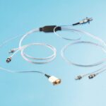
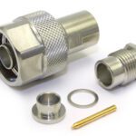
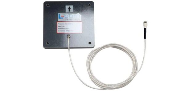
The RFID antenna is the radiating element that links an RFID reader to passive or active tags. It reaches the rest of the system through an RF interface, most often a 50 Ω reverse-polarity TNC (RP-TNC) coaxial connector on fixed UHF readers. This component operates anywhere from 125 kHz to 5.8 GHz, and is most commonly used with cabled, field-replaceable UHF (860–960 MHz) reader antennas. RFID antennas are used by retailers, logistics operators, manufacturers, hospitals, and others.
Origin & Development
The RFID antenna originated with World War II identification-friend-or-foe transponders. Harry Stockman’s 1948 paper on communication by reflected power, with 1970s passive-tag patents and Los Alamos backscatter work defined the modern reader-and-tag architecture. LF and HF coil antennas were first mainly used in animal IDs and access cards. UHF far-field antennas followed, and the 2003 Walmart and U.S. Department of Defense tagging mandates led to widespread use across industries. The 50 Ω RP-TNC has become the de facto reader-side port on fixed UHF readers.
Design Highlights
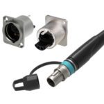
RFID antennas are chosen for band, polarization, gain, and beam pattern, but for connector engineers the deciding factor is the RF interface: any connector or cable mismatch reflects transmit energy straight into the receiver. Return loss, insertion loss, and cable-assembly quality therefore affect read range as directly as antenna gain. RP-TNC dominates cabled UHF reader antennas, with N-type connectors commonly used on outdoor portals, SMA or RP-SMA connectors on compact readers, and U.FL or MHF-type micro-coax on embedded designs. Because these are standard coax interfaces, antennas are largely interchangeable between reader brands, although some readers require approved antennas and professional installation to set transmit power correctly. Some antenna hubs carry power, control, and RF over a single cable.
Markets & Applications
RFID antennas are used in numerous markets and applications, including retail and apparel; logistics, warehousing and airline baggage handling; manufacturing and automotive assembly; aerospace and defense; healthcare; libraries; livestock and pet identification; transportation and access control; contactless payments and ticketing; electronic toll collection; and asset and tool tracking in industrial plants.
Technical Specifications
| IDENTIFICATION | |
| Product / Antenna Category | RFID antenna: reader (interrogator) antennas, reader-integrated arrays and tag (transponder) antennas; by band: LF coil; HF loop / NFC coil; UHF panel, patch, dipole and near-field coupler; microwave patch |
| Manufacturer(s) | TE Connectivity; FEIG ELECTRONIC; Zebra Technologies; CAEN RFID; Times-7; MTI Wireless Edge. Tag antennas / inlays: Avery Dennison; Alien Technology; HID Global |
| Industry Category | RF/Coaxial (cabled reader antennas: RP-TNC; TNC; N; SMA; RP-SMA); micro-coaxial (embedded: U.FL; MHF; MMCX); wire terminal or spring contact (LF/HF coils; internal PCB antennas) |
| Relevant Standards | Air interface: ISO/IEC 18000-63 / EPC UHF Gen2 (860–960 MHz); ISO/IEC 14443, ISO/IEC 15693, ISO/IEC 18000-3 (13.56 MHz); ISO 11784/11785 (134.2 kHz animal ID). Regulatory: FCC 47 CFR Part 15 (§15.203 antenna connector rule; §15.247 for 902–928 MHz); ETSI EN 302 208 (UHF, 865–868 MHz); ETSI EN 300 330 (LF/HF). Connector: MIL-STD-348 interface dimensions; IEC 61169 series |
| ANTENNA & RF CHARACTERISTICS | |
| Operating Frequency Bands | LF 125–134 kHz; HF 13.56 MHz; UHF 860–960 MHz (865–868 MHz EU; 902–928 MHz US); microwave 2.45 GHz; 5.8 GHz |
| Antenna Type | LF/HF: wound or etched inductive coil (near-field magnetic coupling); UHF: linear or circularly polarized patch, dipole, slot, Yagi, phased array; UHF near-field coupler; microwave patch |
| Gain | UHF reader antennas typically 5.5–9 dBi/dBic (examples: 5.5 dBi; 6 dBi; approx. 9 dBic); LF/HF coils specified by inductance and field strength rather than gain |
| Polarization | Circular (left- or right-hand); linear (vertical or horizontal) |
| Beamwidth (3 dB) | Approx. 60°–100° for UHF panels (example: 65° × 65° on FEIG ANT.U290/290) |
| Regulatory Power Limits | US: 1 W conducted, 4 W EIRP (FCC §15.247); EU: 2 W ERP in 865.6–867.6 MHz (ETSI EN 302 208); reader port output example: +30 dBm (PoE) to +33 dBm (PoE+) |
| RF INTERFACE (CONNECTOR) | |
| Reader-Side Port Connector | RP-TNC (Impinj R700: four monostatic RP-TNC female ports mating to RP-TNC male); TNC; N-type; SMA; RP-SMA |
| Antenna-Side Termination | Integrated pigtail terminated RP-TNC or TNC (e.g., 0.3 m; 8 ft); bulkhead TNC or N jack on housing; U.FL / MHF pigtail to PCB antenna; direct spring-contact feed |
| Coupling / Locking Mechanism | Threaded (TNC; N; SMA); snap-on (U.FL; MHF; MMCX) |
| Mating Cycles (rated) | TNC; N; SMA typically 500; MMCX typically 500; U.FL typically 30 (verify per supplier) |
| Body & Contact Materials / Plating | Brass; stainless steel; zinc alloy body with nickel, tri-metal or passivated finish; gold-plated brass or beryllium copper contacts; PTFE dielectric |
| Cable Types | RG58 type (e.g., H155); RG316; thin pigtail coax (up to approx. 0.1 dB/ft); low-loss LMR-240; LMR-400 for long runs |
| Termination Method(s) | Crimp; solder; field-installable crimp-to-cable; PCB solder for internal feed points |
| Impedance | 50 Ω nominal across the operating band |
| VSWR / Return Loss | Antenna: ≤1.3:1 to <1.6:1 typical (1.5:1 ≈ 14 dB return loss); connector and cable assembly should add as little mismatch as possible |
| Insertion Loss | Connector: approx. 0.1 dB or less at 915 MHz when properly terminated; cable at 900 MHz: approx. 1.5 dB/100 ft (LMR-400); approx. 3.9 dB/100 ft (LMR-240) |
| Power Handling | Reader port +30 to +33 dBm (1–2 W); antennas rated higher (example: 10 W on TE S9025PLRTN) |
| MECHANICAL SPECIFICATIONS | |
| Housing Form | Flat panel; patch; PCB-integrated; flexible label or inlay; wire coil on ferrite; pole or ceiling mount |
| Housing Material | ABS; polycarbonate with aluminum backplate (FEIG ANT.U290/290); UV-stabilized radome for outdoor use |
| Overall Dimensions | Tag antennas under 100 mm; reader panels to 300 mm or more |
| Mounting Type(s) | Wall; pole; ceiling; VESA (FEIG ANT.U290/290); bracket; adhesive; PCB |
| SEALING & ENVIRONMENTAL | |
| IP Rating | IP54 to IP67 typical; IP67 on outdoor panels |
| Sealing Type & Material | O-ring or gasket at TNC / N interface; sealed pigtail strain relief; boot or self-amalgamating tape over outdoor mated joints |
| Operating Temperature Range | Typically −20 °C to +70 °C indoor; −40 °C to +85 °C industrial or outdoor (verify per datasheet) |
| EMI / RFI Shielding | Coax shielded with 360° outer-contact termination; antenna radiates by design; dense-reader modes and tunnel enclosures manage reader-to-reader interference |
| MATERIALS & COMPLIANCE | |
| Radiating Element | Etched aluminum or copper; stamped metal patch; wound wire coil; ferrite for HF |
| Dielectric / Substrate | PTFE (connector); FR-4; low-loss ceramic or foam spacers (patches) |
| RoHS / REACH / Halogen Free | Typically RoHS compliant; REACH SVHC and halogen-free status vary by part (confirm per datasheet) |
SUPPLIERS
RF connector and cable-assembly suppliers
TE Connectivity, Hirose Electric, Molex, Phoenix Contact, Radiall, Rosenberger, Würth Electronik, Amphenol, HARTING, HUBER+SUHNER, L-Com
Distributors
CDM, DigiKey, Heilind Electronics, ICC (Interstate Connecting Components), Kensington Electronics, Mouser, PEI Genesis, Powell Electronics, Sager Electronics, TTI Inc.
RELATED PRODUCTS
Microminiature and Ultraminiature Connectors
Like this article? Check out our other Meet the Connector and Connector Basics articles, our Connector and Cable Special Topics Market Page, and our 2026 Article Archives.
Subscribe to our weekly e-newsletters, follow us on LinkedIn, Twitter, and Facebook, and check out our eBook archives for more applicable, expert-informed connectivity content.

- What Is an RFID Antenna? - October 13, 2026
- Connecting the Next Generation of EV Batteries - October 6, 2026
- What is an Antenna Connector? - September 29, 2026