Safety First: Preventing EMI in Medical Devices
Medical devices require connectivity that is safe for operators and patients, while maintaining signal integrity and performance.

Electromagnetic interference (EMI) and electromagnetic compatibility (EMC) are major concerns for electrical engineers in the design and use of electronic equipment. Any environment with multiple electronic devices has the potential for EMI. In the medical arena, which often has a variety of electronic devices for treatment and diagnostics in proximity to each other, this is a special concern because it impacts patients and operators when safety and performance are critical.
EMI, a disturbance caused by electromagnetic radiation from an external source, can appear as noise or distortion that results in partial or complete failure of an electronic device or system. EMC refers to a device’s ability to operate safely in a shared environment without creating or being impacted by EMI. Medical equipment, such as an MRI machines, radio-based therapy equipment, a defibrillator, and a linear accelerator (LINAC) for ionized-based radiation therapy, are susceptible to EMI.
The FDA guidance defines EMC as “the ability of a medical device to function safely and effectively in its intended electromagnetic (EM) environment, including immunity to EM disturbances, without introducing excessive EM disturbances (i.e., emissions) that might interfere with other equipment. Immunity is the ability to protect against unacceptable degradation due to EM disturbances such as radio waves, power surges, radiofrequency (RF) disturbances, and electrostatic discharge (ESD).”
EMI in medical equipment can prevent medical devices from performing as intended and lead to hazardous situations.
- Life-support systems including mechanical ventilators and infusion pumps can experience erratic pulsing, miscalculated drug delivery, and even complete shutdown.
- Imaging machines, electrocardiograms (ECGs), and patient monitors can exhibit distortion in the form of screen flickering, static, or false sensor readings, leading clinicians to miss slight abnormalities or make incorrect diagnoses.
- Pacemakers or implantable cardioverter-defibrillators (ICDs) can unexpectedly pause pacing therapy or deliver unnecessary shocks.
Equipment failures like these can also result in severe regulatory violations, malpractice lawsuits, and costly device replacements.
Industry standards relevant to medical devices identify the maximum allowed EMI generation as well as its tolerance. The primary standard for EMI and EMC in medical equipment is IEC 60601-1-2, which outlines the requirements for testing emissions and immunity. The FDA requires all medical devices to undergo EMC testing. In the EU, all medical devices must have the CE marking, which requires both immunity and emissions testing per this standard.
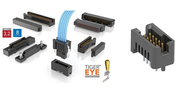
Samtec’s Tiger Eye interconnects are available from DigiKey in a variety of formats and sizes and provide a rugged contact system rated to 10,000+ mating cycles. The TFM-105-01-S-D-A (right) is a 10-position header with 1.27mm pitch contacts.
Connector considerations
Designers must consider multiple factors related to signal integrity and EMI when selecting high-speed connectors in medical applications, according to DigiKey:
- Shorter connectors deliver better signal quality by decreasing the time available for reflections and crosstalk.
- A signal-to-ground ratio of 1:1 is optimal, but for connectors with large pin counts, a ratio of less than 1:1 may be needed for reliable high-speed, single-ended operation.
- Ground shielding of contact pairs is recommended for differential connectors carrying signals of 2.5 Gb/s or faster.
- Following the manufacturer’s recommended termination connection specifications will prevent misalignment, potentially a significant problem on PCBs with multiple connectors. Alignment pin hole diameter tolerances should be ±0.002 inches (0.05mm).
- Board-to-board connectors as well as PCBs can contribute to EMI concerns.
MOOP and MOPP
When medical devices require the patient to be electrically connected to them, the connection between the device and the handpiece, sensor, or surgical tool, poses an often underestimated risk. IEC 60601-1 identifies these as applied parts (AP) and requires at least one Means of Patient Protection (MOPP) and one Means of Operator Protection (MOOP) to ensure that the patient and the operator are protected from electric shock. This protection can be achieved through, for example, safety insulation, defined creepage distance, an air gap, protective earth, or a combination of techniques. MOOP and MOPP are defined in terms of isolation voltage, creepage distance, and insulation level.
One example of state-of-the-art EMC solutions is ODU’s MEDI-SNAP connectors. They offer 2MOPP/2MOOP (double the protection) against electric shock with touch-safe plastic housings and compliance with defined creepage and clearance distances. By incorporating asymmetric contact arrangements and insulating sleeves, ODU implements these protective measures even in compact connectors.
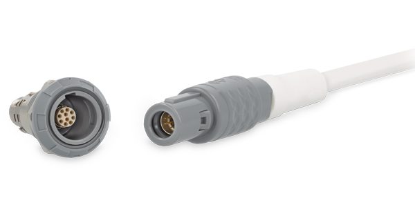
MEDI-SNAP connectors from ODU offer 360° metal shielding (“shielded feedthrough”), which prevents electromagnetic interference both from the outside and from the conductive contacts inside. Tests in independent laboratories according to IEC 61000-4-2 show that ODU solutions withstand electrostatic discharges of up to +/- 15 kV in air and +/- 8 kV in direct contact without sparking or interference.
To learn more about the companies mentioned in this article, visit the Preferred Supplier page for ODU and DigiKey.
Like this article? Check out our Medical Market Page, and our 2026 Article Archive.
Subscribe to our weekly e-newsletters, follow us on LinkedIn, Twitter, and Facebook, and check out our eBook archives for more applicable, expert-informed connectivity content.

- Safety First: Preventing EMI in Medical Devices - September 15, 2026
- Plastic Circular Connectors Product Roundup - September 15, 2026
- Micro, Mini, and Nano Product Roundup - September 8, 2026