Shielded Connectors Improve Electromagnetic Compatibility
Adding EMI shielding to connectors prevents electromagnetic noise from becoming a problem.
Countermeasures against electromagnetic noise. Shielded connectors improve electromagnetic compatibility.
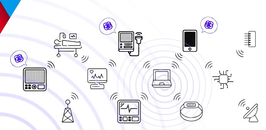
Signal speeds in all types of electronic devices have been getting faster and faster as devices from smartphones to medical equipment to automobiles process greater volumes of data.
Electromagnetic interference (EMI) is a type of unwanted noise in an electrical net generated by an internal or external source. EMI generated from a device’s own internal digital timing signals or electronic components may cause failure of other components within the same system. This is an intra-system electromagnetic compatibility (EMC) problem.
EMI causes problems for design engineers who develop high-performance electronic devices in which high-density electronic components are mounted. When interconnects (or, connectors) are used in these types of devices, EMI shielding is often needed for these connectors to prevent electromagnetic noise from becoming a problem.
No electrical noise from connector to the outside Electromagnetic Interference (EMI)
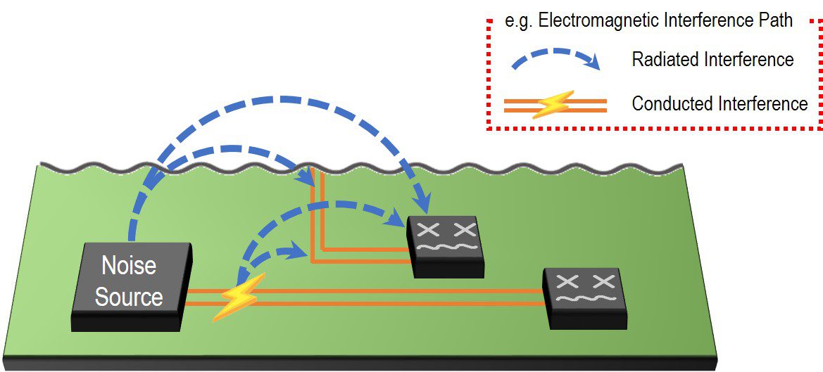
Two common paths of EMI
- Radiated interference occurs when high-frequency signals traveling on a conductive surface (or wire or PCB trace) generate a time-variant electromagnetic field. This electromagnetic field radiates and can be detected some distance from that surface. The shorter the distance between the source and the adjacent surface (or wire or PCB trace), the larger the coupled field that can be detected.Since the adjacent surface is conductive, voltages and currents will be induced by the electromagnetic field. Solutions for this normally require shielded enclosures, cables, and connectors. If any one part of the system is unshielded, it will be a point of radiated EMI leakage.
- Conducted interference occurs when intentional or unintentional signals in a circuit directly travel by conductor (e.g., wire or PCB trace) from one place to another in such a way as to interfere with the proper operation of the destination circuit or device. Incoming power lines are one such example of conducted interference. In this case, use of line filters, capacitor networks, and similar methods are employed to separate (or condition) the intended voltage signals from the interference voltages.
EMI-mitigating technologies eliminate electromagnetic noise from the connector by including an appropriate grounding structure and cover. This includes the mounting position of the signal contact tails with metal shields. Micro-coaxial, micro-RF, board-to-board, and FFC/FPC connectors with shielding are widely used to prevent EMI in high-performance electronic devices equipped with wireless communications functions, such as Wi-Fi, GPS, and LTE.
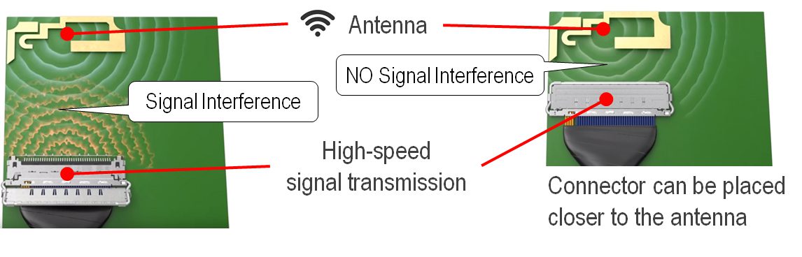
This diagram shows the proximity of the connector and the cable with and without signal interference. ZenShield® from I-PEX eliminates electromagnetic noise from the connector by including an appropriate grounding structure and cover.
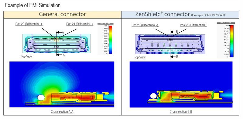
A 360° shielding design prevents electromagnetic noise radiation not only from the contact points of the plug and receptacle, but also from the board mounting part (SMT positions) of the signal terminals. In addition, both the plug and receptacle shields are connected at multiple points when the connectors are mated and properly grounded to the board. This ensures enough ground return paths for the current generated in the metal shields of the connector and works to suppress the emission of electromagnetic noise from the shield.
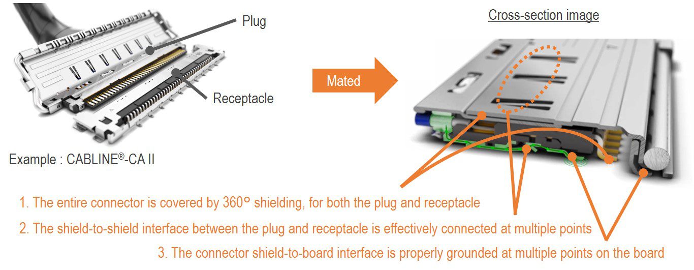
Three connector design features enable effective EMI mitigation
- The entire connector should be covered with 360° shielding, for both the plug and receptacle, the board mounting part (SMT positions), as well as the contact part of the signal terminal.
- The shield-to-shield interface between the plug and receptacle should be effectively connected at multiple points.
- The connector shield-to-board interface should be properly grounded at multiple points on the board to improve the ground return path.
With these design features, the connector itself provides significant mitigation of EMI. Connector shielding technologies give design engineers more flexibility for board design by allowing the connectors to be placed in close proximity to sensitive subsystems such as transmit/receive antennas for wireless communications.
To learn more about ZenShield connectors, visit I-PEX.
Like this article? Check out our other Connector Basics articles, our Materials Market Page, and our 2024 Article Archive.
Subscribe to our weekly e-newsletters, follow us on LinkedIn, Twitter, and Facebook, and check out our eBook archives for more applicable, expert-informed connectivity content.
- Shielded Connectors Improve Electromagnetic Compatibility - June 18, 2024
