The Role of Connectors in High-Performance Vehicle Systems
High-performance vehicle technologies require new electrical design strategies and advanced connectors to meet these challenges.
As the transportation world integrates high=performance vehicle technologies into vehicles of all types and transitions to electromobility, the traditional decentralized electrical system architecture is reaching its limits. The complexity and high-speed properties required for technologies such as advanced infotainment, safety systems, autonomous driving, and vehicle-to-infrastructure communication networks requires new design strategies and new connectors to meet these challenges.
Vehicle electrical systems: decentralized, domain, and zone architectures
The traditional decentralized vehicle architecture consists of up to 100 control units, each assigned a defined function, such as controlling the engine control unit (ECU), airbag, ABS/ESP, seat adjustment system, or climate controls. Every controller works autonomously and communicates with other control units via gateways. As vehicle features are added or improved, each new functionality adds a control unit. All vehicle types, from delivery van fleet vehicles to buses to automobiles, have seen dramatic changes in recent years, and increasing the number of functions has significantly increased the wiring and interconnect content in every vehicle.
The control units in the domain architecture are grouped into different functional areas, each responsible for a specific area of the vehicle, such as the drivetrain, infotainment system, or safety features. A standalone high-performance computer (HPC) executes the primary control of a domain and coordinates the control units within its domain. The safety domain, for example, oversees control units for driver assistance systems, ABS/ESP, and steering systems. Domain architecture reduces the number of control units, which reduces the wiring and installation effort needed compared to traditional decentralized architecture, effectively reducing weight and costs. Additional functions can easily be integrated in upgrades or new designs.
In zone architectures, structuring is not based on domains, but rather on local zones. For example, multiple functionalities are bundled in one zone within a vehicle. Functions such as drivetrain and infotainment can be combined and processed in one zone controller. A central HPC executes primary control of the various zone controllers, reducing the number of control units and the amount of wiring that goes along with them by 50%.
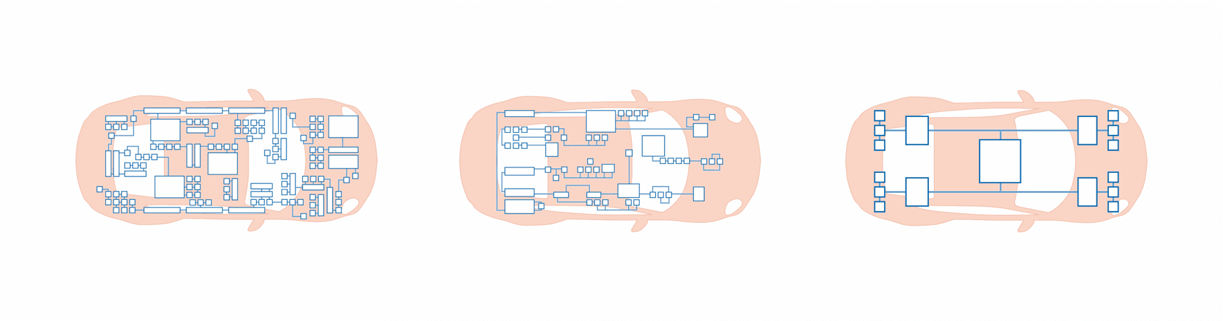
Figure 1: Schematic representation of high-performance vehicle electrical system architectures. Illustration: ept GmbH
High reliability and performance requirements
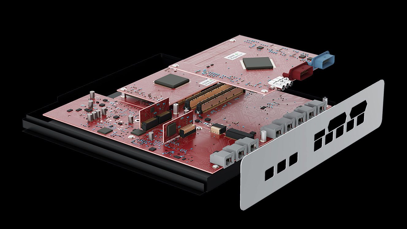
The HPC and its corresponding interconnects must be designed to the highest performance requirements. For example, processing the imaging and sensor data in safety systems for autonomous driving requires secure high-speed data transfer rates with short latency times. At the same time, the signal transmission must not fail under any circumstances. High-performance, fast, and, above all, reliable data transfer rates – sometimes under adverse environmental conditions – are requirements for the connectors in these systems.
A signal’s “readability” can be illustrated with an eye diagram which shows whether a transmitted signal in the receiver can be uniquely assigned to the digital states 1 or 0. To this end, a signal passes through a defined transmission path, is recorded with an oscilloscope, superimposed, and displayed. This way, signal courses can be mapped overlapping. According to theory, the transitions of the logical states are infinitely steep and the signal lines are exactly superimposed. External interference factors and internal impairment of the signal pairs flatten the signal rise while the amplitude level changes.
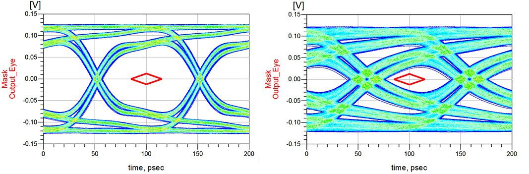
Figure 2: The eye diagram is used to evaluate the signal quality of a digital data transfer rate. Illustration: ept GmbH (Colibri)
What is known as the “eye mask” can be seen in the middle of the diagram. The signal cannot be clearly assigned in this area.
Both eye diagrams illustrate the influences of cable length and impedance using the 16+ Gb/s and 10 Gb/s ept Colibri plug connector. This example illustrates how to realize a significant increase in signal integrity by further developing the contact design. By using a shorter cable length and an impedance of 100 Ω, the eye of the 16+ Gb/s Colibri variant is able to form more clearly than is the case with the previous 10 Gb/s Colibri variant – the signal pairs can be clearly interpreted.
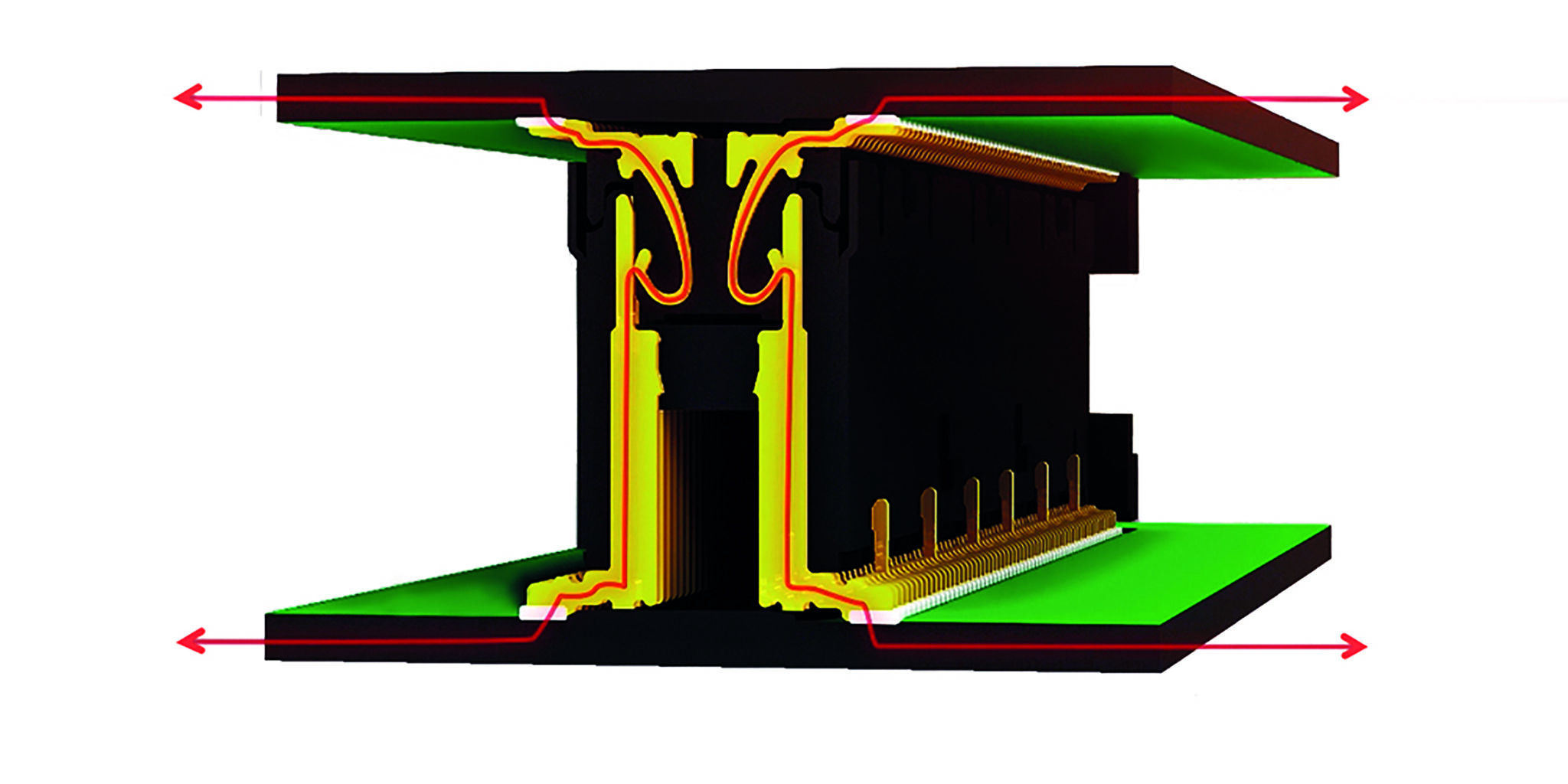
Figure 3: The Colibri’s optimized contact design enables low-loss high-speed data transfer rates. Illustration: ept GmbH (Colibri)
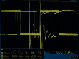
High-speed signals require special signal protection since they are particularly susceptible to electromagnetic influences. In this context, a connector can act both as a source of interference and as a sink. A shielding plate will protect the sensitive signals from external influence.
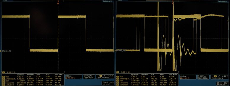
Figures 4, 5: Signal interference when using the shielded (above) and unshielded (below) connector
Illustration: ept GmbH (Colibri)
The connector can be described by considering the electrical conditions in both functions – source and sink – with the coupling inductance LK as the EMC parameter. The henry (H) is used for expressing this value. This applies to both interference immunity and interference emission. If the induced voltage (Uind), the voltage of the generator (UGen), and the generator’s constant (kGen) are known, the specific maximum permissible coupling inductance (L) can be determined for an application using the following formula:
LK = Uind / (UGen x kGen)
The coupling inductance also helps the user define the appropriate connector in terms of its electromagnetic compatibility and helps avoid cost-intensive and time-sensitive trial and error tests. Here is an example: A case-specific maximum coupling inductance of 47 picohenry (pH) was determined at a voltage of 4.4 kV for an HDMI signal. If the value is above this, the signal can accordingly no longer be transmitted without interference.
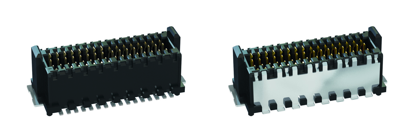
Figure 6: Connectors in unshielded (left) and shielded (right) version.
Illustration: ept GmbH (Zero8)
Electromagnetic influences endanger the transmission of high-speed signals. Connectors, especially in high-performance vehicle applications, are exposed to extreme environmental conditions such as vibration and shock. The connector must be particularly robust to ensure that signal transmission remains uninterrupted even in harsh environments. In this context, it is primarily the contact design, contact system, and termination technology that play a decisive role.
Strategic contact design for harsh environment reliability
Traditional two-piece connectors have one male contact and one female contact. However, the male connector may lift off of the female connector in the event of strong shock. To prevent such an interruption of contact, a double-sided female connector can be used to provide redundancy and thus contact reliability, as the second female contact ensures signal transmission at all times via at least one contact point (Fig. 5).
Double-sided female contact without (left) and with (right) exposure to shock.
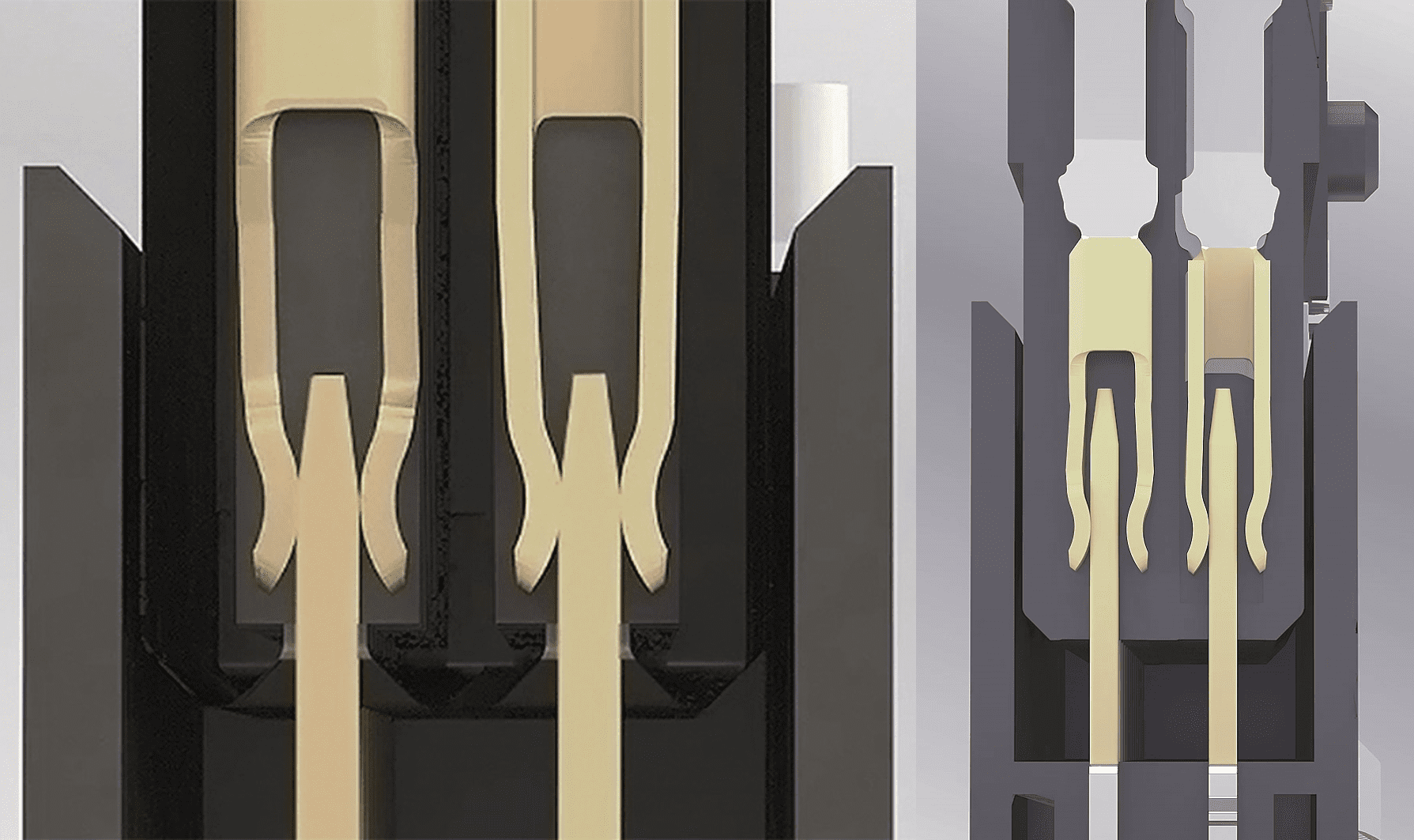
Connectors with a “gender-neutral” contact system are even more robust. The special feature here is the identical contact geometries of the connector pairs – the plug and the socket. Accordingly, both have both a female and a male contact. Thus, each pin is contacted by two female contacts, and the plug and socket are interlocked and cannot lift off of each other. While a double-sided female connector always ensures at least one contact point when under a mechanical load, the interlocked geometries in gender-neutral contact systems ensure that signal transmission always runs via two contact points. This high degree of redundancy thus enables maximum contact reliability (Fig. 5).
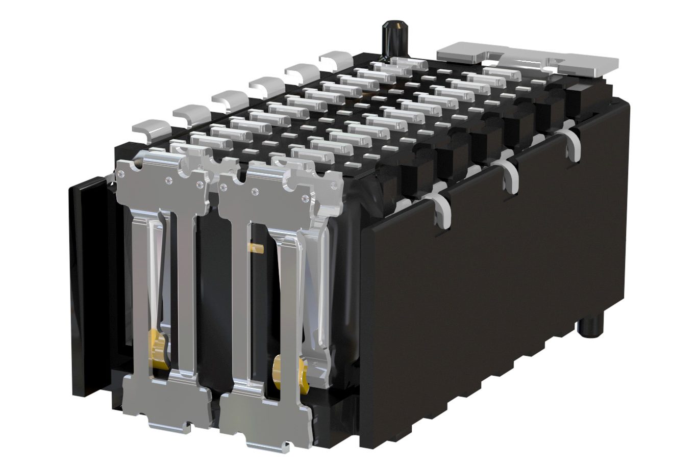
Figure 7: A cross-section of the Zero8 connector shows the gender-neutral contact system.
To achieve a durable connection between the PCB and a connector, we recommend using surface mount technology (SMT) as a termination technology. Solder paste is used to solder the connectors onto the PCB’s specified connection surfaces: the solder pads. The solder is first melted and then hardened in what is called a reflow oven. SMT allows stable connections to be made between the connector and the PCB. However, a few criteria must be met in order for this to happen. First, the correct ratio of solder foot, solder pad, and solder paste must be maintained in order to create a solder joint that is compliant with the IPC A-610. This is the only way to enable a high-quality connection according to IPC class 3, meaning it is suitable for use in high-performance vehicle electronics. This class stipulates that signal transmission failures must never occur. An optimal soldered connection is recognizable by the uniform formation of the meniscus. The entire circumference of the contact must be enclosed with solder meniscus in order to achieve the best possible retention forces on the PCB. (Figure 7).
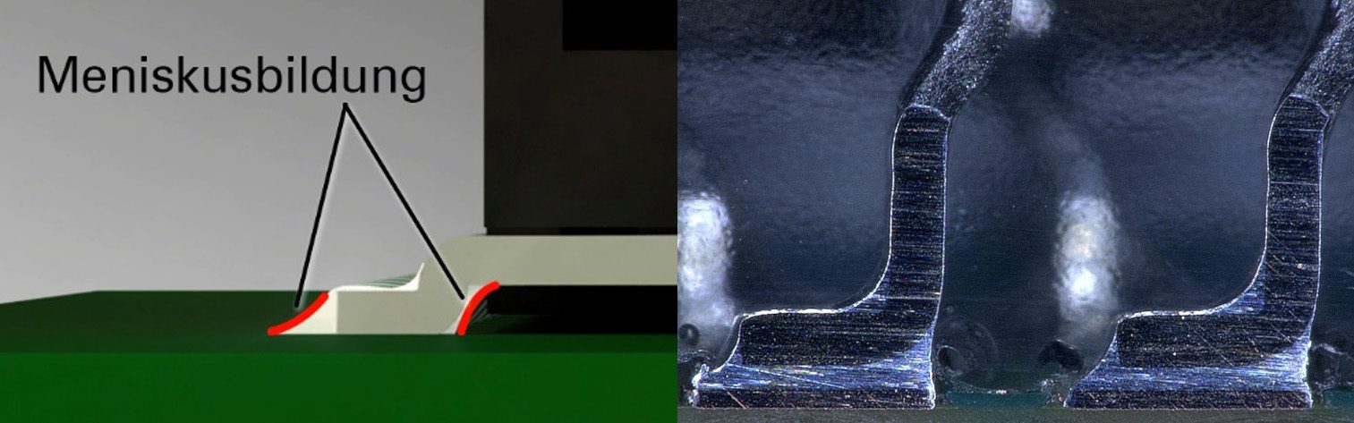
Figure 8: Uniform formation of the meniscus around the solder foot
The contact feet must be coplanar in order to achieve an excellent connection. This coplanarity is subjected to a fully automated in-process inspection.
At first glance, the role of connectors in high-performance vehicle systems seems to be fading into the background due to the reduced number of control units. However, a closer look reveals that their role is becoming more important precisely because of this shift toward centralized data processing via HPCs. Never before has reliability in signal transmission been more important.
Visit ept connectors to learn more about high-performance connectors.
Like this article? Check out our other High-Reliability, High-Speed and Connected Vehicle articles, our Transportation Market Page, and our 2024 Article Archives.
Subscribe to our weekly e-newsletters, follow us on LinkedIn, Twitter, and Facebook, and check out our eBook archives for more applicable, expert-informed connectivity content.
- The Role of Connectors in High-Performance Vehicle Systems - September 10, 2024
