Severe Environment Testing for COTS Connectors
COTS connectors have an attractive price point and availability, but they may not hold up to harsh environment challenges. Rigorous testing helps engineers specify non-MIL-Spec connectors that can provide high reliability.

By Brian Niehoff
Electronic devices are proliferating in harsh operating environments across every industry. As a result, many OEMs require extensive testing on the interconnects used in those systems to ensure they function as intended under challenging conditions. Suppliers of high-reliability interconnects may contract with outside testing facilities to ensure products meet regulatory and standards specifications. Test labs will conduct select testing procedures or a full complement of harsh environment tests.
Some full-service component suppliers also provide rigorous in-house testing. Samtec, for example, developed its Severe Environment Testing (SET) initiative to give product designers the confidence to specify its commercial off-the-shelf (COTS) products for use in high-reliability systems. The military/aerospace, space, automotive, transportation, industrial, and medical industries typically require additional testing that isn’t normally conducted on COTS products. The intent of SET is to bridge the testing gap between a full MIL-STD product and a COTS product. SET testing starts with standard qualification tests and expands upon those specifications with more demanding test processes that ensure reliability in the field.
Whether conducted in-house or through a testing lab, test processes focus on six key areas: Durability, Temperature Cycling, Mechanical Shock/Vibration, Non-Operating Class Temperature, Electrostatic Discharge, and Dielectric Withstanding Voltage.
Durability
Mating/Unmating/Durability are common standard qualification tests. It is essential that a connector set can be mated and unmated without a degradation in the signal. The Mating/Unmating/Durability test demonstrates the capability of the connector set to perform as designed even under high-stress conditions. For instance, high heat and high humidity can often lead to material degradation, and it is important to know that the connector can withstand it. In a standard Mating/Unmating/Durability test, the relative humidity (RH) is held at a range of 90% to 98% for a duration of 10 days, with 100 mating and unmating cycles, at a temperature of +25°C to +64°C. For SET, the RH is increased to 100% with 250 mating and umating cycles, for 10 days (240 hours), at a temperature of +25°C to +64°C. Low Level Circuit Resistance (LLCR) is used as the baseline for this test before it begins. LLCR is tested, the connectors are then measured for mating/unmating forces, cycled 250 times, and LLCR is tested again. If the connectors have a max delta of less than 15 mΩ, they will move to the next test sequence.
Temperature Cycling
Another critical aspect of any environmental test involves ensuring performance of the connector set under temperature shock. Temperature cycling assesses the connector’s ability to withstand extreme temperature changes. In some operating environments, temperatures can change dramatically within minutes. Normally, a temperature cycling test takes a connector set from -55°C to +85°C through 100 cycles, with a 30-minute dwell at each temperature. The SET version of this test increases the temperature range to -65°C to +125°C through 500 cycles, with a 30-minute dwell at each temperature. During this test, the connector sets are tested for LLCR to look for increases in resistance through the system.
Mechanical Shock / Random Vibration / LLCR and Event Detection
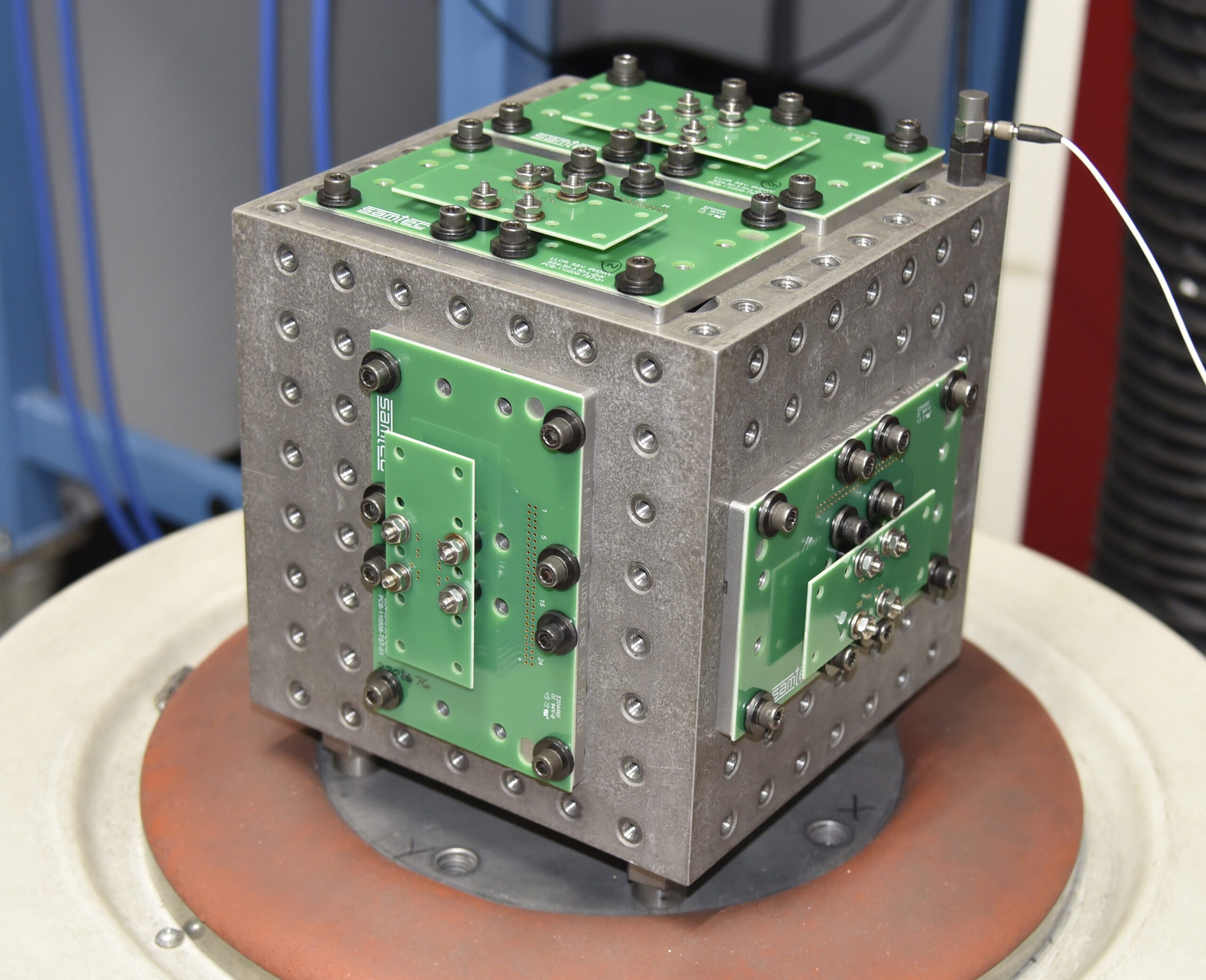
Mechanical shock test setup
The overall goal of Mechanical Shock/Random Vibration testing is to measure a connector set’s performance under conditions that simulate mechanical shocks and random vibrations found in many harsh operating environments. For mechanical shock, the standard version of this test uses a 100G peak shock for six milliseconds, half-sine. The SET version uses 40G peak shock for 11 milliseconds, half-sine. LLCR is used before and after the test to gage the effects of the test and to look for changes in the contact system resistance. The standard random vibration test uses 7.56 gRMS for two hours per axis; the SET version of this test using 12 gRMS, 5 – 2000Hz for one hour per axis. During this test, event detection is used to continuously monitor the contact set for discontinuities.
Non-Operating Class Temperature
Not only is it important to know at what temperature range a product can operate at peak levels, it is also important to know under which conditions a product can be stored. Electronics in a system can sit dormant while not in use, and there must be assurances they will operate when needed. For Non-Operating Class Temperature testing, the product is LLCR tested, exposed to -55°C to 105°C for 100 cycles, then tested for LLCR again, exposed to -65°C to 125°C for 100 cycles, and finally tested for LLCR again. This assumes the product maintains a delta of ≤ 5 mΩ for LLCR from the start of the test to the end. This is a stable product for those temperature ranges and the engineer can be confident the connector will function properly.
Electrostatic Discharge
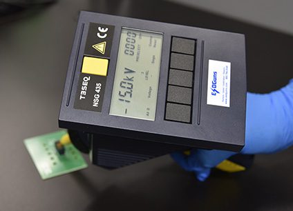
ESD tester
Electrostatic discharge (ESD) is not a typical test for passive electrical connectors. In severe environments, however, there are times when system designers need to know how the components will handle ESD. During an ESD test, the connector is tested both mated and unmated, with visual inspections before and after testing to determine if damage occurred. For this test, a visual inspection is sufficient to determine if the connector passed. Connectors are passive devices, with no active components, and the only damage that could occur would be to the plating. If the plating remains unburned or unmarked, the test has been passed. This test is based on EN61000-4-2 from VITA 47. The ESD events range from 0 to 15 kV as discharged through a 150-pf capacitor through a 330-ohm resistor. The connectors are exposed to 5, 10, and 15 kV (10 times at each level), and then are visually inspected for damage.
DWV at Altitude
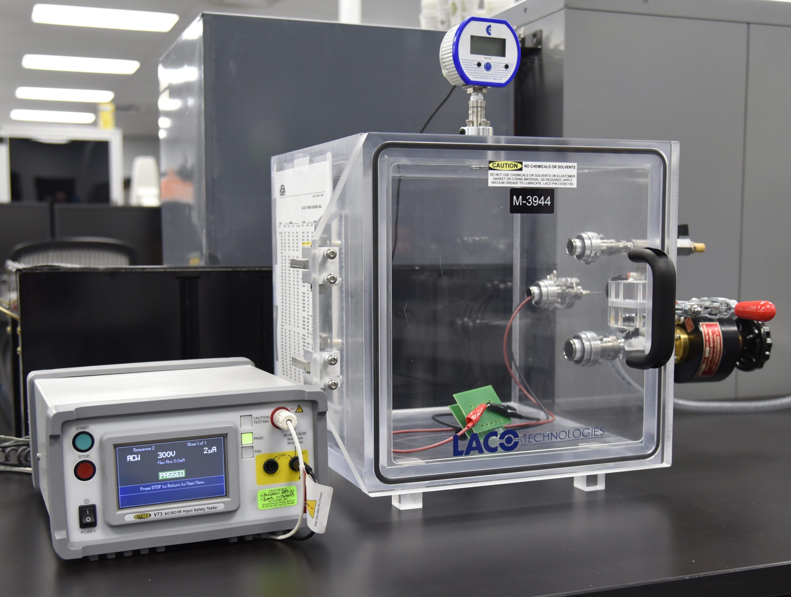
DWV altitude chamber
Dielectric withstanding voltage (DWV) is a common electronics test. Testing at an altitude of 70,000 feet (21,336 meters) adds to the difficulty of the test. With the reduction of air in the chamber, the main dielectric (air) has been reduced to simulate the altitude of 70,000 feet with a test voltage at 300 VAC. In a typical DWV test, a product is pushed until the breakdown voltage. This is the point at which the connectors will have an electrical arc. To determine the testing voltage, the breakdown voltage will be multiplied by 0.75. The test voltage is applied to the connector set for 60 seconds. The product passes the test if no electrical arcs occur.
Conclusion
SET was developed using VITA 47.0 – 47.3 and input from OEMs concerning test information needed on COTS products. A standard qualification test combines tests such as LLCR, Humidity, Temperature Cycling, DWV, and Mechanical Shock and Vibration. SET takes these standard qualification tests and expands the specifications required to pass the test. By doing so, this gives the designer confidence that the connector can be used in severe environments for their application.
Visit Samtec online to see Severe Environment Test reports and learn about harsh environment testing.
Like this article? Check out our other test equipment, and harsh environment articles, our Datacom Market Page, and our 2022 and 2021 Article Archives.
Subscribe to our weekly e-newsletters, follow us on LinkedIn, Twitter, and Facebook, and check out our eBook archives for more applicable, expert-informed connectivity content.