Future-Proof High-Speed Data Transmission with Fiber Optic Splice Boxes
Fiber-optic splice boxes ensure continuously reliable data transmission in real-time via fiber optics, enabling cloud-based technologies such as the Internet of Things to bring us to a state of ubiquitous computing.
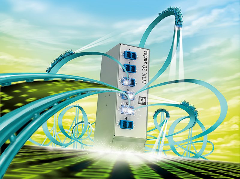
Splice boxes bundle connected end devices on the active side to the loose tube cables of the backbone cabling.
In principle, data does not exist on the internet or in the cloud. Instead, computing activities are housed in end devices such as smartphones, PCs, and industrial automation devices. These devices are connected to each other in local networks (LAN – local area network), broadband telecommunication networks (MAN – metropolitan area network), national networks (WAN – wide area network), and ultimately, worldwide networks (GAN – global area network). The data streams of all end devices are bundled into transmission paths that are designed for high performance, have immunity to interference, and deliver failsafe performance. Fiber optics (FO) is the ideal transmission media.
Fiber optics has many advantages
Optical data transmission via FO enables data rates of up to 40 Gb/s over paths that are many kilometers long. This transmission method does not have a negative effect on adjacent cables and is also resistant to electromagnetic interference. Because of these features, fiber optics has been the backbone transmission medium in local networks since the early 1990s. The compact cables were simply pulled through the existing power supply ducts or blown in with compressed air.
As broadband networks expanded and many more communication devices — including data centers – came online in the early 2000s, the end of the FO path moved closer and closer to the local end-user network. Optical multi-fiber cables with MPO or MTP male connectors became the de facto standard, especially as trunk lines both to and from data centers.
The last section of the transmission path to the end device, often called the last mile, still consists primarily of twisted copper cables with two (twisted pair) or four (star quad) cores. On the passive infrastructure side, fiber optics and matching pin connector patterns, such as ST, SC, and LC, are in place. At the same time, the active consumer or converter side has copper conductor and pin connector patterns such as M12 or RJ45.
Fiber Optic Splice boxes make transitions
Fiber optic splice boxes or splice distributors form the transmission and distribution points between these networks. The FO cables from data centers or control centers, which are often designed as loose-tube cables, enter splice boxes and split into different FO connections to a media converter or directly to the recipients in the control cabinet.
These passive junctions, or hubs, offer clear advantages. If a device, such as a media converter, is replaced or added on the active side, the system operator will not have to replace all the established infrastructure cabling. The multi-fiber trunk line continues to ensure interference-immune data transmission in the backbone. Only the significantly shorter, less expensive patch cables between the junction and the active components need to be replaced or added. This ensures that the level of investment in the backbone – such as cables, lines, and distributors – remains unchanged. The new active device can also be commissioned more quickly because the patch cables that need to be replaced are directly accessible in the control cabinet.
Conserving space with DIN rail devices
Unlike 19-inch components, DIN rail splice boxes are not installed directly in extensive data centers. Instead, they are installed inside compact field control cabinets, in control rooms, or in offices. These compact devices can be snapped into place directly next to other devices on the DIN rail.
Splicing is a critical step in the process, but this is where the fiberglass can be contaminated, broken, or inaccurately connected unless properly handled. An easily accessible tray to hold the fiber optics is essential to preventing these problems. At the same time, the minimum approved bend radii for fiberglass place tight limits on the device size.
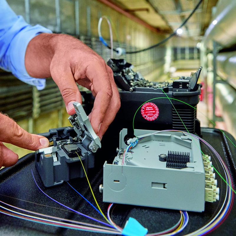
A device with conveniently dimensioned pigtails can simplify thermal splicing while protecting operability and compactness. Since the wires are already connected to the respective front connections, only the open fiber ends need to be connected to the fibers of the loose tube cables. This minimizes potential problems and reduces downtime.
Flexible but uniform design
LC quad, LC duplex, SC duplex, ST duplex, LSH duplex, and LSH duplex connections are available for different applications or devices connected on the active side. A standardized pin connector patterns for fiber categories OM1 to OM4 as well as OS2 splice boxes provides high flexibility and investment security on the active side.
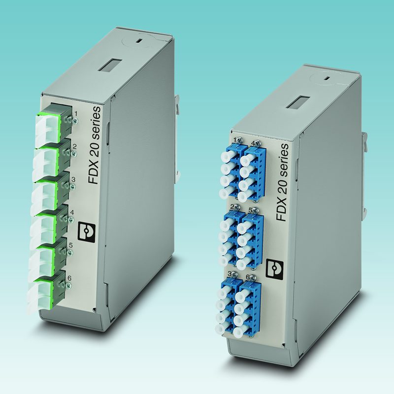
The splice boxes are available with front connections for 6 ST duplex, 6 SC duplex, 6 LSH duplex (left), and 6 LC quad (right). If the front panels have a uniform design, the function and assignment to the active device side is clearly identifiable, improving the overview and making front operation intuitive. Control cabinet providers can group functional or manufacturer-specific units.
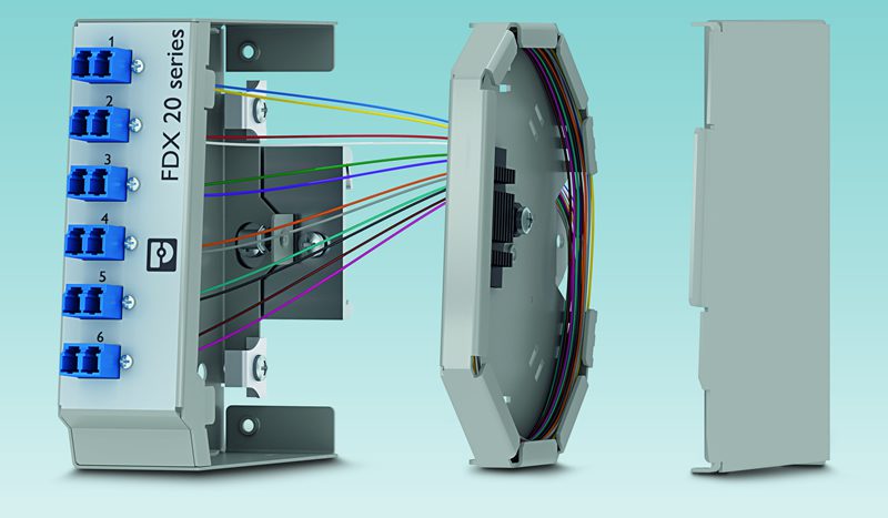
The FDX 20 series features a large splice tray in a compact, uniform device design.
Fiber simplifies installations
When planning a FO cabling system, consider the type of connection technology that will be used. Fusion splicing, field assembly, or a pre-assembled plug-and-play connection systems offer distinct advantages to users. Fusion splicing and field assembly may require expertise and special equipment, such as a fusion splicer, various tools, measuring devices, and different consumables, as well as more time and labor. Plug-and-play systems don’t require specialists or additional equipment, saving time in the field. If installation is taking place in a harsh environment, such as a power generation plant or substation, another important aspect is the high degree of protection required for the connection components, such as IP67.
Connectors with 24 positions: the unique key design prevents mismatching.
A FO cabling system with an integrated MT ferrule makes it possible to package up to 24 fibers compactly and safely. The high-density connecting cables are ideal for fixed installation in underground conduits and cable ducts and, with the factory-assembled connectors, provide direct connection between cabinets.
DIN rail splice boxes are key junctions between the FO-based backbone cabling and the copper-based data cabling in control cabinets and in the field. As purely passive components, they secure the investment in existing FO cabling and simplify the replacement of active components. Splicing trays, compact bending radii, and user-friendly front connections for established pin connector patterns are important features for reliable, efficient operation in control cabinets. Plug-and-play solutions solve many problems associated with installation, connection technology, and data transmission.
Learn more about high-speed network solutions at Phoenix Contact.
By Frank Kölske, Product Marketing Data Connectors, Phoenix Contact GmbH & Co. KG, Blomberg and Olivia Koicuba, Product Marketing Specialist, Phoenix Contact USA
Like this article? Check out our other Fiber Optics, High-Speed articles, our Datacom Market Page, and our 2023 Article Archive.
Subscribe to our weekly e-newsletters, follow us on LinkedIn, Twitter, and Facebook, and check out our eBook archives for more applicable, expert-informed connectivity content.