Custom Designs for SWaP-Focused Connectors
The SWaP initiative employed by the US military and NASA has helped connector manufacturers focus on improving smaller and lighter connectors, in particular for custom designs.
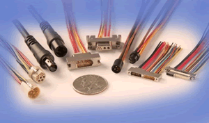
 As we demand our circuits do more and in smaller packages, we still need reliable power and signal transfer. Today’s designers have a number of new tools and options for cable and connectors that help them adapt to a rapidly changing electronics industry. Customized connectors can be designed to include sets of 3A and/or 5A power lines adjacent to micro and nano signal lines to meet SWaP expectations. These devices offer smaller, lighter-weight interconnect systems with a mixed variety of signal and power levels that still perform well in rugged and extreme environments. For example, we now use custom connectors that include combinations of USB 3.0 digital circuit speeds and are simultaneously running power sources that use 5A currents for highly portable military and airborne equipment.
The SWaP initiative employed by the US military and NASA has helped connector manufacturers focus on improving smaller and lighter connectors. By adding power pins inside the same connector with signal pins, the designer reduces the number of cable and connectors he has going to and from his electronic module. This is essential in new space and remote-controlled drones as well as portable systems used by ground troops. The number of signal pins and power pins will vary from application to application and each design may be unique unto itself. The good news is that tools today can reduce both cost and time to design for these new mixed signal connectors. Custom is no longer a bad word in the application-specific connector world.
Designing Custom Connectors is Easier
Updated design tools that use solid models can speed up concept drawing and provide the system engineer a visual and size specification in a matter of days. Connector designers have a broad family of COTS and standard designs already available from which to hinge changes. Often a standard connector can be changed into a custom application quickly with the use of an alternate insulator. Some suppliers stock solid insulator plugs and can machine first-article connectors to hurry the design to completion. Costs are significantly lower than with the older methods of full-custom design. When a new connector metal shell system is needed, the supplier can use automated CNC machines to rapidly cut early prototypes directly from data received from his solid modeling software.
Find a Good Supplier

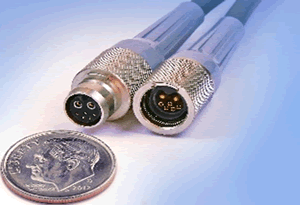
Omnetics circular breakaway connectors
Finding a good a supplier for SWaP-focused custom connectors can be rather straightforward. First and foremost, look for a manufacturer with connector experience in all of the key areas. The company should have worked with the combination of microminiature sizes, ruggedized reliability, and multiple designs using power and micro or nano signals in one connector. Ask for examples of current products that handle both power and digital signal in one connector. Secondly, simply ask for a solid model of what you are thinking about by giving some of the criteria listed below. The manufacturer should be able to deliver the models in a reasonably short time. Suppliers with experience and technical capability will rise to the top.
Look for signal integrity and test capability. System designers should ensure that a combination of test requirements are available from the supplier. As digital signal speed increases, ask to talk with the supplier’s signal integrity engineer and request high-speed test data, simulations, and/ or eye diagrams of its products. Also ask for the supplier’s capabilities for testing high current levels and current surges to ensure the power portion of the connector meets expectations.
Key electrical considerations for the system design engineer include some of the following (each affects both the cable and connector design):
- What is the amperage demand for the system that the connector is serving, and will two wires handle demand and ground? If not, how many wires? Is there a de-rating factor on current limits? Is there a set dielectric-withstand voltage needed to prevent breakdown?
- Is the signal system in the connector analog or digital?
- What is the speed of each signal in the cable, and is there an impedance match required?
- Will it include high-speed digital signals that require differential signal wiring in the cable?
- What is the electromagnetic environment the cable and connector must work within and how much shielding is necessary to ensure high signal integrity?
- Will signal crosstalk become a problem between signals within the system?
Key physical considerations are just as important. They include:
- Is the mechanical design able to receive round, rectangular, or stacking connectors?
- Does the connector go through a panel into a device or is it on the end of a cable connecting onto a probe or sensor. If it is a probe, is it vulnerable to shock, crush, and even chemical exposure?
- Is the connector pin/socket mating system designed, tempered, and plated to meet high-reliability performance used in space and military-type applications?
- How much room is available and is the shape critical?
- Is there exposure to high shock and/or continuous vibration?
- Are there extreme temperature or environmental considerations to prepare for?
Custom Power and SWaP Connectors Available Today
Established micro and nano connector manufacturers that have offered military specification 32139 and 83513 now offer a wide range of design variations from their existing products. Both rectangular and circular formats are readily available.

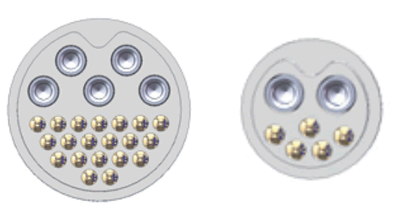
Custom circular connector insulators
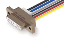
 Custom power D-shaped micro connectors at .050mil spacing, a popular design for new applications, evolved from established standard D-shaped connectors. Omnetics’ high reliability Micro-D connectors are a good example and are available with mixed power/signal contact layouts. The number of power and signal contacts may be specified to provide the greatest flexibility in circuit design while ensuring that the connector is kept to the absolute minimum necessary size. This hybrid combination eliminates the need to have a D-sub type or other higher-power connector next to the Micro-D, making it easier for the operator who now only needs to mate a single connector. The power contact can handle 20 – 24AWG wire and is suitable for currents of 7A to 10A. These hybrid connectors can be available in wired or through-hole PCB-mount termination types. The wired power contact is an insertable/removable type contact, which can be optionally supplied for customer termination, except for through-hole leads that are permanently installed. These options can be packaged in the conventional screw-together-type Micro-D shells or the Omnetics quick-latching Micro-D form factor.
Custom connectors with mixed power and high-performance signal contacts have come of age. The move away from older standard designs has been empowered by the use of new tools and solid model designs to package highly established standard pin-and-socket elements with years of high-reliability experience. Devices use military-grade materials, internal elements, and design standards to achieve SWaP performance.
Author Bob Stanton is director of technology at Omnetics Connector Corp.


