What is a MIL-DTL-27599 Connector?
The MIL-DTL-27599 specification covers two series (Series I and Series II) of miniature, high density, quick disconnect, bayonet coupling, circular, environment resistant electrical connectors. They are intermateable with the applicable Series I and Series II connectors of MIL-DTL-38999. Series I mates with 38999 Series I, and Series II mates with 38999 Series II.
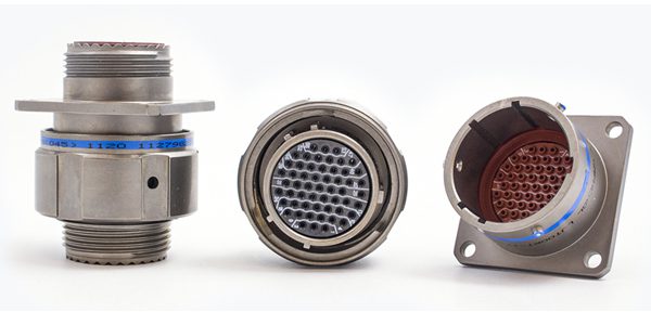
Amphenol MIL-DTL-38999 Series I LJT are available in solder versions as both Commercial and Military qualified to MIL-DTL-27599
Technical Standard
MIL-DTL-27599 is a U.S. Department of Defense specification (preparing activity DLA-CC) and maintained by DLA Land and Maritime (qualifying activity: VQ).
Design Highlights
- The two 27599 series will not intermate with each other.
- MIL-DTL-27599 connectors have molded-in solder contacts, whereas MIL-DTL-38999 typically uses removable crimp contacts.
- They are supplied under a MIL-STD-790 reliability assurance program.
- The specification is inactive for new design after December 7, 1998. The most recent revision is MIL-DTL-27599E w/Amendment 1 (31 Jul 2017).
Markets & Applications
MIL-DTL-27599E Series I connectors are intended for general application within weapon systems where a quick disconnect coupling system is required for blind mating or other mating problem areas.
MIL-DTL-27599E Series II connectors are intended for general application within weapon systems which are not subjected to high vibration or severe wind and moisture problem (SWAMP) areas. These connectors are not scoop-proof; connectors are lightweight.
Technical Specifications
NOTE: Standards undergo periodic review and updates. Even within standards, connector manufacturers offer distinctive features and configurations. Please consult supplier data sheets to verify that a given product meets your application requirements.
| IDENTIFICATION & STANDARDS | |
| Governing standard | MIL-DTL-27599E w/Amendment 1 (31 Jul 2017); Qualified products are listed on QPL-27599 and carry the JAN or J marking |
| Issuing body | U.S. DoD. Preparing activity DLA-CC; qualifying activity DLA Land and Maritime-VQ |
| Series | I: scoop-proof. II: non-scoop-proof, low silhouette. Not intermateable with each other. |
| Category | Circular MIL-spec, miniature, high density, bayonet, solder contact |
| Part Numbering | MS20026 + class + shell size + finish + insert arrangement + contact style + polarizing position (example: MS20026 T 15 A 18 P A) |
| MECHANICAL SPECIFICATIONS | |
| Classes | P (potted, with potting form) and T (general duty, pressurized receptacles) |
| Shell sizes | Series I: 9 to 25 (odd). Series II: 8 to 24 (even) |
| Shell material and finish | Machined or impact-extruded aluminum alloy. Finishes: A (cadmium over nickel), B (olive-drab cadmium), T (nickel fluorocarbon polymer), Z (zinc-nickel). |
| Mounting | Plugs are straight, with or without spring fingers. Receptacles are box, wall or jam-nut mount. |
| Locking | Bayonet, with a detent that gives an audible click |
| Keying | Five integral keys; main-key position Normal (no letter in the part number) or alternates A, B, C, D. |
| Mating cycles | 250 |
| CONTACT SPECIFICATIONS | |
| Contact sizes | 22D, 22M, 22, 20, 16 |
| Contact material and plating | Pin: copper alloy. Socket: beryllium copper. Gold, 50 µin minimum, over an underplate (silver underplate prohibited). |
| Termination | Solder cup only (style P pin, style S socket). Contacts are molded in. |
| Contact arrangements | Per MIL-STD-1560 |
| ELECTRICAL CHARACTERISTICS | |
| Current rating | See manufacturer’s spec sheet |
| Dielectric withstanding voltage | Sea level, Vac RMS: service rating M 1,300, I 1,800, II 2,300 |
| Insulation resistance | Over 10,000 MΩ; 100 MΩ minimum after humidity |
| Contact resistance | Per SAE-AS39029 |
| Impedance and data rate | Not defined (the 50 Ω in the document applies only to the EMI test fixture) |
| SEALING & ENVIRONMENTAL | |
| Sealing | Class T: pressurized receptacles; air leakage limit of 1 atm·in³/hr applies to all Class T receptacles.
Class P: potted, with RTV cavity fill; air leakage limit of 1 atm·in³/hr applies to MS20029 only. Silicone or fluorosilicone gaskets. IP rating not applicable. |
| Operating temperature | -65 °C to +150 °C (finish A); -65 °C to +175 °C (B, T, Z) |
| EMI shielding | Series I: 85 dB minimum, 100 MHz to 1 GHz. Series II: 45 dB minimum over the same range. The shielding requirement applies to mated shells with spring fingers and EMI backshells. The dB values vary with frequency. |
| Vibration | 10 to 2,000 Hz, 10 g. |
| MATERIALS & COMPLIANCE | |
| Insulator | Reinforced epoxy resin or other rigid dielectric |
| RoHS / REACH | Not addressed. Finishes A and B use cadmium, which RoHS restricts; T and Z do not. Where tin is used, it must be alloyed with at least 3% lead. |
| Test standards | EIA-364 series, MIL-STD-790, MIL-STD-810 method 508, SAE-AIR4789 |
Related Products
Like this article? Check out our other Meet the Connector and Connector Basics articles, our Military and Aerospace Market Page, and our 2026 Article Archives.
Subscribe to our weekly e-newsletters, follow us on LinkedIn, Twitter, and Facebook, and check out our eBook archives for more applicable, expert-informed connectivity content.

- What is a MIL-DTL-27599 Connector? - October 20, 2026
- How We’re Creating Connections for Life - October 16, 2026
- What Is an RFID Antenna? - October 13, 2026