Five Considerations When Specifying RF Coaxial Connectors for High Speed with Signal Integrity Applications
RF/microwave technologies are increasingly used in high-speed digital data exchange applications and the mix of connector and cable technologies is becoming more complex. In the next generation of wireless technology, higher data rates and the accompanying need for high signal integrity will require higher performance capabilities in all RF interconnection.

To meet these high frequency and performance needs, RF interconnect product design and manufacturing is constantly advancing and expanding. The latest RF designs meet the high frequency performance, high durability cycles, and high data rate capability required for the next generation of wireless networks, but system designers need to pay special attention to five factors.
1. Protect high signal integrity
Signal integrity refers to the challenge of ensuring all connectors and cables carry uncorrupted signals. Variations in power and ground voltage and crosstalk between cables introduce noise which can seriously affect operation and data transmission.
RF interconnect for high-speed digital applications requires high levels of isolation and protection from all electromagnetic interference to protect signal integrity. The design of the connector, including the base material and plating type used, is a major factor in ensuring low interference. Effective shielding and connector quality are therefore of great importance.
2. Minimize return loss
In cable assemblies, connectors, and PCB traces, structural return loss can occur due to manufacturing imperfections and design errors. Spotting design flaws that might produce structural return loss can ensure the component or interconnect system will work as designed and that signals will not be degraded as they pass through an interconnect.
A conductor that has some non-uniformity will also have some impedance variations. This creates reflections along the length of the conductor, and the magnitude of these reflections can be described in terms of return loss. This type of return loss is called structural return loss. The impedance variations along the length of the conductor are compared to the conductor’s rated or desired impedance when calculating structural return loss.
Structural return loss is common in poorly manufactured coaxial cables, where variations in impedance along the cable length cause signal reflections for a wave travelling along the cable. These impedance variations can arise from variations in conductor thickness, spacing between the shielding, or both. It is therefore vital that only quality cables are used to avoid structural return loss.
3. Designs systems that limit impedance
In a PCB, a number of design problems can produce the same effect. Variations in trace geometry due to length tuning methods, vias along interconnects, and inconsistent return path/trace spacing due to warpage create impedance discontinuities along the length of a transmission line. If an interconnect is not designed correctly, incident signals reflect back to the source from these impedance discontinuities.
In general, impedance discontinuities and structural return loss will arise if signal paths are not properly designed. Impedance discontinuities may be capacitive or inductive, depending on the geometric variations along a conductor, producing larger structural return loss in specific frequency ranges.
4. Choose high-quality RF connectors
To further combat structural return loss, high quality RF coaxial connectors are required to continue the superior signal path. A poorly designed connector will cause the same issues with continuity of signal path, resulting in an increase in return loss.
A well-designed RF coaxial connector made with the correct materials for the application will ensure the signal path is uninterrupted from the first connector, through the PCB and cable, to the last connector, and on to the next device.
When developing a new RF connector design for use on a PCB, the launch has to be considered right from the start. The transition from an air dielectric and a printed circuit substrate can create problems that cannot be fixed with a board redesign later; they must be mitigated at the start.
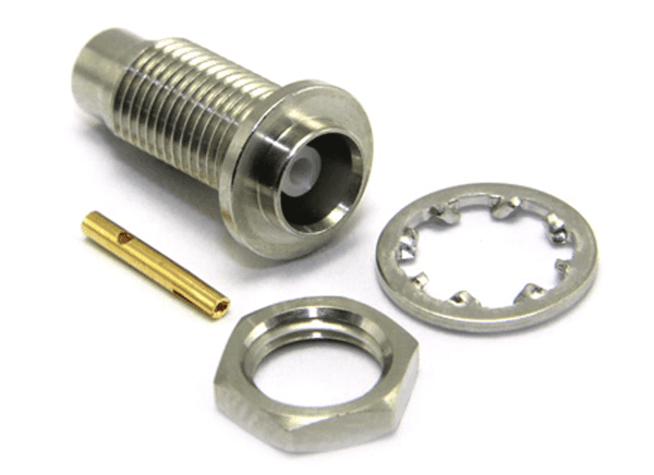
COAX Connectors’ MCX 50 Ohm Rear Mount Bulkhead Solder/ solder jack with a white bronze finish enables connectors to be mounted on an aluminum panel without the risk of corrosion.
5. Collaborate with components suppliers to design for density
Now that the signal is on the board, transitioning onto an uninterrupted transmission line is vital. Close cooperation with the board manufacturer is critical at this stage.
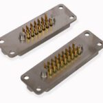
Among the most commonly used interfaces for high-speed applications are MCX, MMCX, and SMA. These subminiature connector series offer precision design, high frequency capabilities, and good signal integrity. Their compact size and large number mean that most high-speed applications can be catered to and large numbers of connectors can be installed in a compact area.
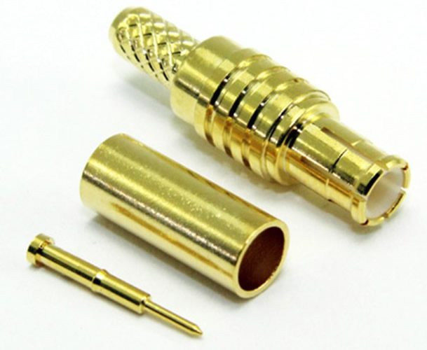
COAX Connectors’ MCX 75 Ohm full crimp straight plug has annealed crimp zones for lasting performance. Their size makes them ideal for antenna and board connections where space or weight is important.
Because many high-speed digital applications have high interconnect densities, small pitch distances are required. Hence push-type connectors and connector/cable assemblies that allow a large number of connections are common.
Reducing the delay between the separate parallel digital signals is necessary and requires very closely matched transmission line lengths.
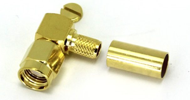
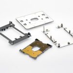
COAX Connectors’ SMA Solder/Crimp Reverse Polarity right angle plug for use when space is restricted when mating.
Resonances usually affect return loss and crosstalk and must be minimized. In connectors this is achieved by careful design of the wipe between the two mating pins and providing an effective return path with low return loss.
Designing a system that maximizes signal integrity while minimizing return loss and impedance loss, calls for the highest levels of RF connectors. Collaborating with your supplier can help you achieve your performance goals and be ready for the inevitable increases in speed and performance that the next generation of equipment will require.
Visit COAX Connectors to learn more.
Like this article? Check out our other RF and Coax, High-Speed articles, our Datacom Market Page, and our 2023 and 2022 Article Archive.
Subscribe to our weekly e-newsletters, follow us on LinkedIn, Twitter, and Facebook, and check out our eBook archives for more applicable, expert-informed connectivity content.