Maintaining Connections in Compact Board-to-Board Applications
A system cannot sustainably operate if all components are constantly at maximum stress capacity. The ticket to longevity lies in designing a component system that can tolerate electrical fluctuations as well as physical movement of the hardware.

Data centers, data storage, data display on screens – managing the amount of data and the many venues we need to interpret and display it is a colossal challenge. Transferring highly demanding signals while maintaining connection is no easy feat. Technology has come a long way, but designers are searching for solutions to meet data’s escalating needs, such as sensors with lightning-fast reaction times to real-time stimuli, smaller hardware with massive data storage capabilities, and faster communications within networks and between multiple stacks of PCBs.
Applications demand higher and higher speeds and multi-faceted capability, but the hardware to accomplish this must fit into smaller, more compact devices. Since the 1990s, the average size of connector pitches has decreased from 2.54 mm or more; 1.5 mm, 0.4 mm, and 0.8 mm are now common sizes. Smaller high-speed hardware also reduces costs, reduces component redundancy, and minimizes the amount of real estate a component takes up on the board. But the smaller a device is, the more tolerant its hardware must be of vibrations, oscillation, and electrical fluctuations and shocks.
Surface mount technology (SMT) designs shine in installations that need to reduce in size but still maintain identical, if not improved, performance. Surface mount technology can be a solution for small spaces because it allows the printed circuit board to be populated on both sides, as well as offering small grids. Boards can even be designed to fit together via right-angled connectors or via cabled connectors for added flexibility. With standard press-in technology, a narrow grid of only 0.5 mm would not tolerate the physical forces acting during the press-in process, and neither would a printed circuit board with assembly on both sides. Surface mount technology makes these configurations possible.
The challenges of establishing peak performance high speed
A system cannot sustainably operate if all components are constantly at maximum stress capacity. The ticket to longevity lies in designing a component system that can tolerate electrical fluctuations as well as physical movement of the hardware.
Physical movement can occur in the form of oscillations and micro-movements, but the primary culprit most associated with failure in maintaining an established electrical signal is vibration. Traditional SMD (surface mounted device) connectors with blade-and-spring contact designs often cannot withstand vibration without deforming or disconnecting. There are many alternative contact choices, such as genderless connectors (a blade and spring is on both the socket and the plug, rather than solely on one or the other connector), dual beam contacts with a significant wipe length, and press-fit contacts, which can enable connectors to withstand vibrations. Another option is a pottable connector, one that can be encapsulated within a suitable material that acts an actual physical barrier, preventing movement and disconnection.
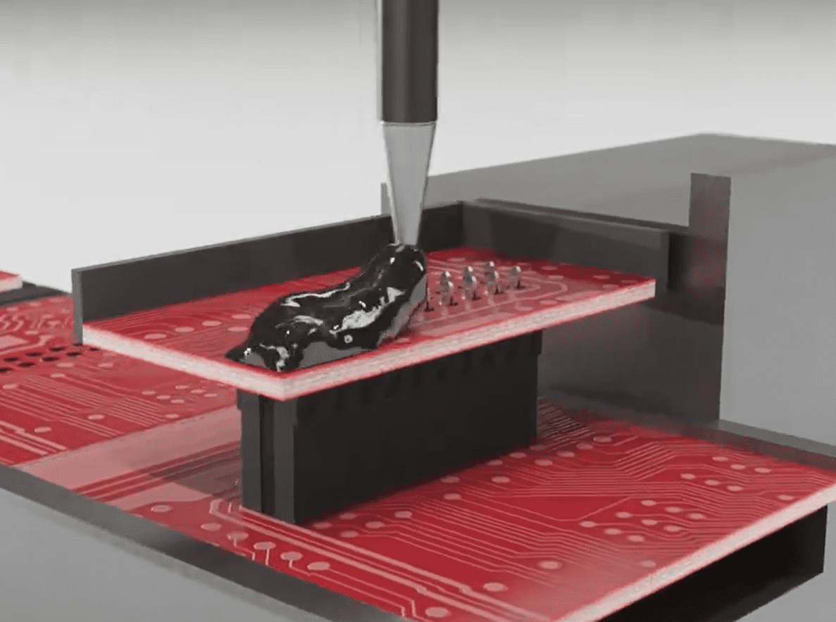
ept’s Flexilink connector has a two-sided design with press-fit contacts on both sides, seen here during the potting process. Press-fit alone offers a very secure connection, but the connector can also be potted for extra resistance to shock, moisture, any possible corrosive agents in the air or in liquid form, as well as vibration.
Challenges: misalignment compensation and tolerances
The trend of miniaturization has made critical flaws that occur during operation even more noticeable; tighter tolerances are less forgiving of flaws.
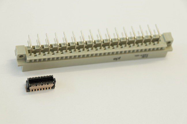
ept’s Zero8 SMT connectors. Twelve;; individual connectors, each with a 0.8 mm pitch, are able to operate successfully on a single board due to their float capability, or tolerance, of 0.4 mm while mated. This allows for great scalability and flexibility in design.
How a connector performs on the board during active operation is an obvious focus when designing PCBs. Addressing the challenges resulting from the initial installation is another equally critical step that is often neglected or left out of consideration until the testing phases. Flaws that occur during mating can not only cause permanent damage to the board and the components, they may also cause an otherwise high-performance design to perform with an unreliable signal and lackluster data rates. Using the correct tooling for the press-in of a connector can greatly reduce the chance of faulty mating. Using a machine rather than hand-placing components onto a board can bring better results. Also, opting for a connector designed with misalignment possibilities in mind can mitigate later losses. Depending on the type of connector and its contacts, offsets, vertical, and horizontal tolerances should be considered. For tolerances and misalignment compensations, the industry standard is about 0.5 mm or less and about 2°, but connectors that outperform these numbers are now available.
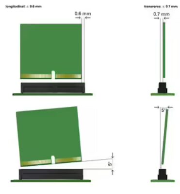
ept’s EC.8 connector is capable of data transmission rates of up to 28 Gb/s. When a daughter card is inserted, EC.8 tolerates an angular offset of up to 5° in a longitudinal and transverse direction. An offset of 0.7 mm vertically and 0.6 mm parallel to the longitudinal axis of the connector is also tolerated.
Interference to signals
For miniaturized designs, adding connectors with built-in EMC shielding should be seriously considered. High-frequency signals are exceedingly susceptible to interference from unwanted electromagnetic influence. Interference can come from surrounding components, electronics outside of the system, and even the connector itself can cause unwanted electrical interference to components nearby. Regardless of where the electromagnetic effects are coming from, a small pulse can be enough to falsify or impede a signal and prevent the receiver from clearly interpreting the digital states.
This can be particularly critical in high-speed, high-stakes technologies such as nuclear energy, automatic breaking or crash-avoidance technology in the automotive sector, and medical imaging systems such as CT scanners, MRI devices and digital X-ray machines – these types of technologies often need to communicate up to 20 Gb/s of data in real time, flawlessly. Opting for a connector with an EMC shield is critical because failure due to avoidable signal interruption is not acceptable.
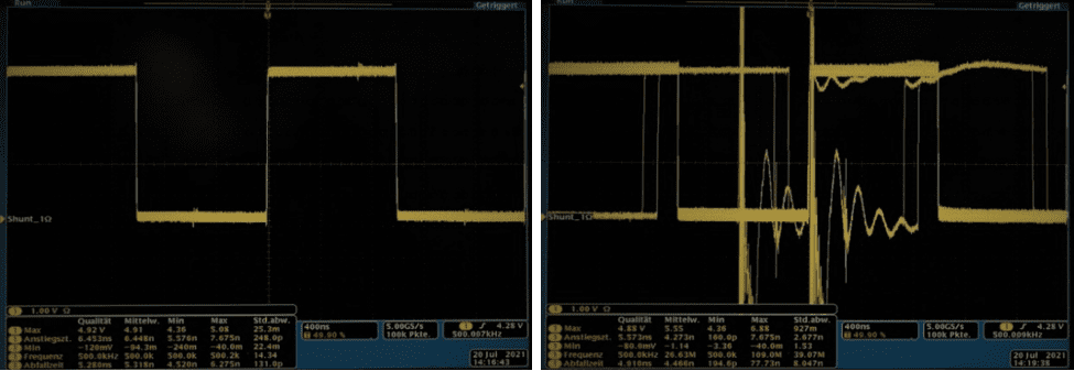
A visual representation of electrical interference. Interference is minimized via a shielded connector (left) and unshielded connector (right). On the right, the signal has been interrupted to such an extent that it has become unusable.
Surface mount technology offers a first-hand advantage by speeding up rapid deployment of new technology via lightning-fast data transfer. It can be difficult to operate a high-speed connector without also considering the component’s scalability and flexibility within a given PCB design. A component offering high speeds may not necessarily be compact or have robust capabilities to tolerate the challenges that inevitably occur during operation. To minimize stress to the connector and stress to the PCB, features that offer rugged tolerance to vibration, connectors with high tolerances during mating and operation, and EMC shielding should be considered.
To learn more about high-speed and surface mount technology solutions, visit ept usa.
Like this article? Check out our other How To Specify, Data Centers and High-Speed articles, our Datacom Market Page, and our 2024 Article Archive.
Subscribe to our weekly e-newsletters, follow us on LinkedIn, Twitter, and Facebook, and check out our eBook archives for more applicable, expert-informed connectivity content.