The Universal Genius of M12 Connector Technology
When it comes to sensor and actuator applications, the M12 circular connector with A-coding is the first choice. Regardless of whether it is a matter of transmitting signals, data, or electrical power, M12 connectors have become indispensable as an interface for device networking.
M12 circular connectors have become the common standard for industrial plug connections. This compact, standardized interface is available from many manufacturers, which makes it attractive for industrial applications ranging from the transmission of signals and data to power transmission. The robust, mechanically, and environmentally resistant M12 connector is named for the 12 mm nominal diameter of the locking thread. The wide range of applications for M12 connectors is reflected in the number of mechanical codings (unique mechanical profiles of the housing for specific applications) that comply with the standards (DIN EN 61076-2-xxx) for the respective areas of application.
Dust and liquids cannot harm the M12-A circular connector from Würth Elektronik eiSos. The connectors comply with protection classes IP67 and IP68 and are suitable for use in harsh environments.
The A-coding mechanical shape is the origin of all M12 codings; all other mechanical locking systems have developed from it, which is why there are different codings (A, D, L, X, S, etc.), each with different numbers of contacts available. Although M12 interfaces can have from 2 to 17 contacts, in practice, the most used are three, four, five, eight or twelve pins. The number of pins depends on the various requirements. For example, sensors and power supply applications require three and four pins, whereas Profinet and Ethernet applications require four and eight pins, and Fieldbus, CAN bus and DeviceNet typically require four and five pins. Twelve pins are required for sophisticated signal transmission. Table 1 shows an overview of the protocols and number of connector pins required at the physical level.
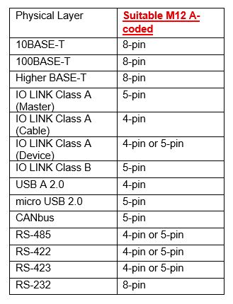
Table 1: Overview of the physical level of the M12-A coding. Würth Elektronik offers circular connectors with M12-A coding with 4, 5 or 8 pins.
Sophisticated connection systems
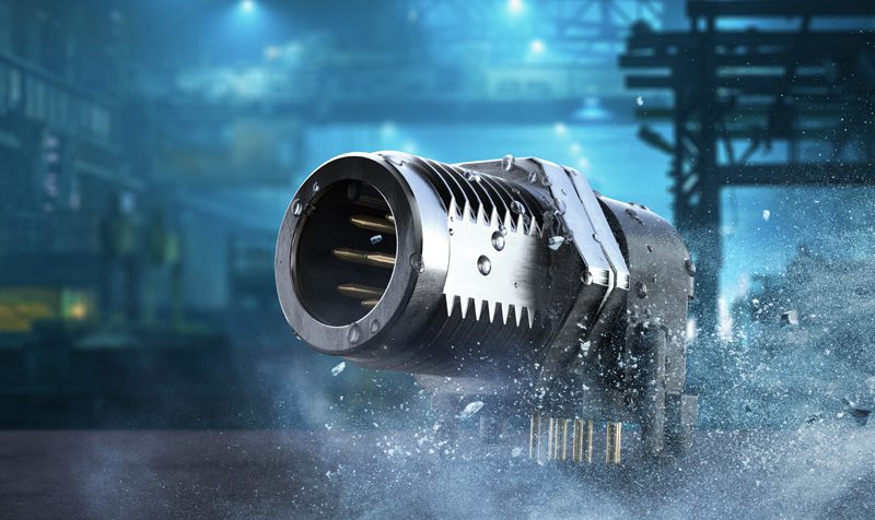
M12-A stands for signals with the option of DC power supply, which are particularly suitable for fieldbus applications in industrial automation. The WR-CIRCM12 family with a screw lock housing and cable assembly is available with 4, 5 or 8 pins. Areas of application can be found in industrial environments, particularly in automation and robotics, as well as in the field of renewable energies, communication technology and mechanical engineering. In addition, the panel and field wireable models of the M12 connectors are cULus-certified (UL2238). All M12 connectors provide minimum protection to IP67 or IP68 against the ingress of dust, dirt, and water.
Ensuring reliable Ethernet communication
Sensor and actuator applications depend on the fast and error-free transmission of digital signals via cable. The basis for this is Ethernet Over Twisted Pair (EOTP), which is considered one of the most important physical layers for Ethernet. It serves as the basis for the EtherCAT, EtherNet/IP, Profinet, CC-Link IE, Powerlink, Sercos III, and Modbus TCP protocols.
Although M12A is not the original connector on which the EOTP interface was developed, it is still possible to use the connector in various adaptations. For example, the eight-pin M12 circular connector can be used as a replacement for the RJ45 in an ANSI/TIA-568 Category 3 cabling system used for the 10BASE-T Ethernet interface at 10 Mb/s. The Cat 3 cable consists of four twisted pairs with a typical differential impedance of 100 Ohms. Figure 1 shows the recommended assignment when wiring an RJ45 (8P8C modular plug) with an M12 A-coded circular connector. On the other hand, when wiring an M12 A-coded circular connector with an M12 A-coded circular connector, a pin assignment as shown in Figure 2 is recommended.
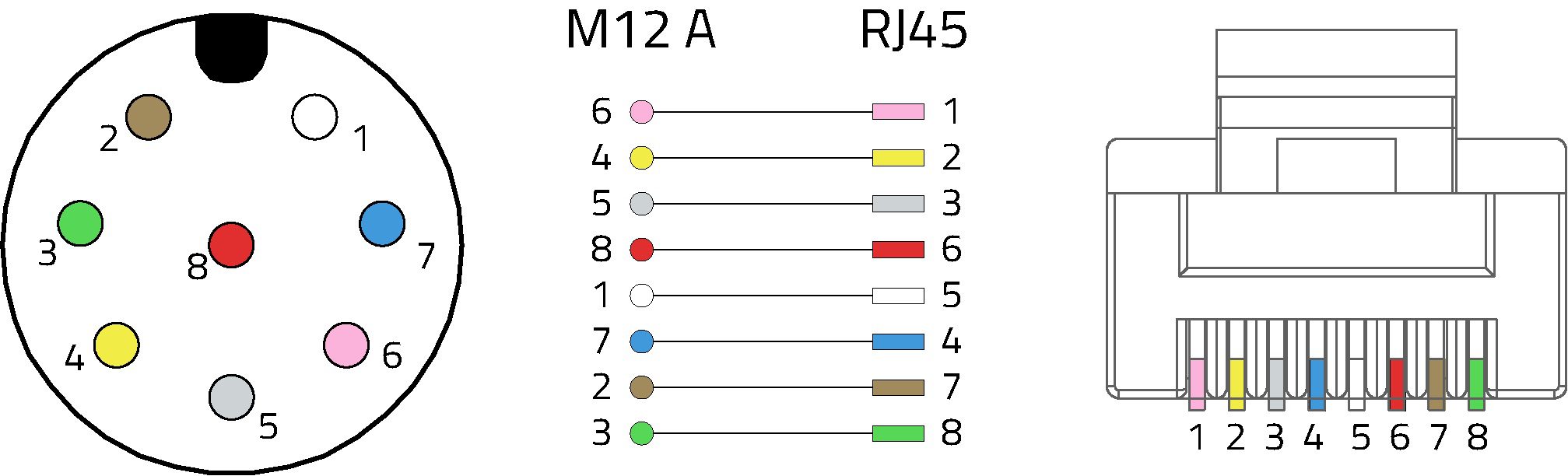
Figure 1. 10BASE-T transmission: Recommendation for wiring an RJ45 (8P8C modular plug) with an M12 A-coded circular connector.
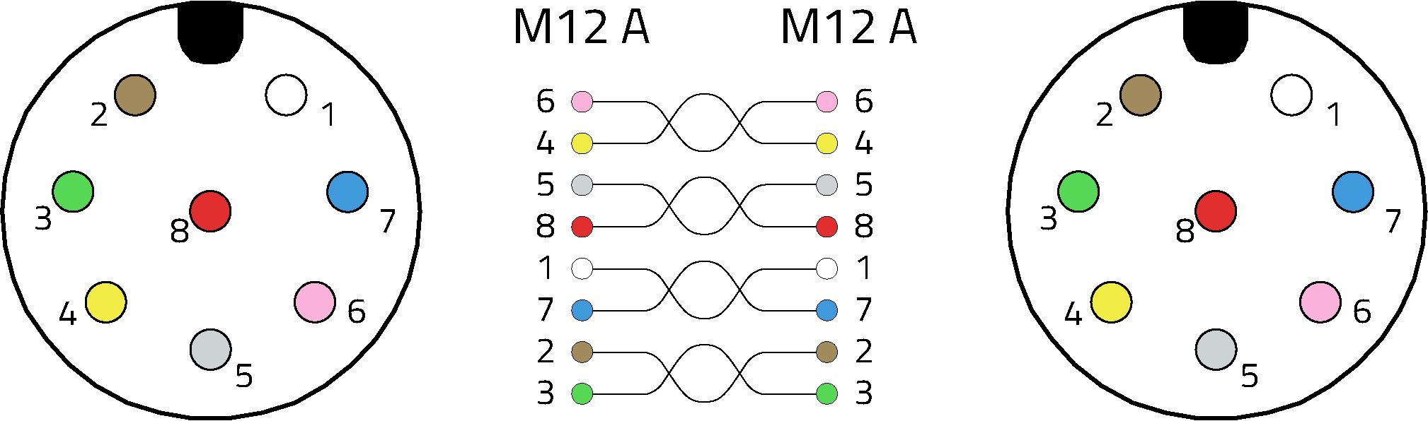
Figure 2. This is the recommended pin assignment from M12-A to M12-A for 10BASE-T transmission.
This pin assignment minimizes the delay offset between contacts of the same pair. This wiring is a widely used configuration for A-coded M12 EOTP cabling. Although 10BASE-T uses only two pairs for signal transmission, it is not advisable to have only two pairs in the cable or to use a four-pole A-coded circular connector, as this can lead to confusion with other widely used applications. On the other hand, a D-coded connector is recommended for two-pair EOTP cabling with M12. Other Fast Ethernet variants are also possible, specifically 100Base-T for applications up to 100 Mb/s, which require D-coded circular connectors with two-pair cables, or higher Base-T for data rates of up to 10 Gb/s. For the latter, however, X-coded circular connectors with four-pair cables are required.
Can higher clocked EOTP standards be implemented alternatively with M12-A coding without compromising on speed and signal integrity? For 100 Mbit/s EOTP standards, it is possible to create an interface with an A-coded circular connector by following the same pin assignment as for 10-BASE-T. Signal integrity must be considered when designing such an interface. The entire cable assembly, including the connectors, must conform to ANSI/TIA-568. Each of the plug/socket pairs and the cable itself have a budget for loss and crosstalk that must not be exceeded. It is recommended to test the S-parameters of such an interface, which mainly depends on the cable category and the cable length. Even at significantly higher data rates of up to 10 Gb/s, it is possible to create an interface with an M12 circular connector with A-coding by implementing the same pin assignment as for 10-BASE-T and 100-BASE-T and applying the same signal integrity considerations. Such an interface will generally have a much shorter cable length.
A wide range of applications
This is by no means the end of the range of applications for the robust M12-A circular connectors. For example, the IO-Link communication system can be used to cleverly connect intelligent sensors and actuators to an automation system in accordance with IEC 61131-9 – using four- or five-pin A-coded M12 circular connectors that are connected to a three- or five-wire 20-metre cables. The connection on the three-wire cable is referred to as “Class A” and the connection connected to a five-wire cable as “Class B.” The device connection can be a captive cable or a four- or five-pin M12 A-coding, depending on the desired cross-compatibility.
The M12-A can also handle USB connections. For USB version 2.0, it can be used both as a power supply and as a high-speed data bus. The M12-A circular connectors are suitable to make a robust USB cable assembly. Two power connections for V-bus and GND as well as a twisted pair with a differential impedance of 90 ohms for the USB signal must be considered in cable assemblies for USB 2.0. If the connection is a mini or micro-USB plug, the ID pin can be wired as such on a five-pin M12 A-coded round plug. The connector is shielded with the shielding braid of the cable. USB cables are usually between 1 m to 3 m long.
M12 connection technology is ideally suited as an intermediate link for industrial bus systems, especially for CANbus, RS-485, Profibus and the physical levels RS-422, RS-423 and RS-232. While the CANbus was originally designed for use with a small D-SUB connector, the five-pin M12-A coded round connector is a popular interface for the CANbus. Only the CAN_H and CAN_L signal pair, which is wired to pins 4 and 5, is mandatory. The device can be supplied with power in this configuration. Twisted signal cable pairs with a nominal impedance of 120 ohms is used for electrical transmission.
The RS-485 physical layer is often used for the industrial protocols Modbus, OSDP, SSCP, SCSI-2, SCSI-3, Profibus, Nanoréseau, DMX 512 and AES 3. Figure 3 shows a typical RS-485 pin assignment for five-pole A-coded cables. Alternatively, four-conductor shielded cables can also be used. The wiring largely depends on the required power supply, but always includes at least the symmetrical TxD/RxD pair in positions two and four to minimize the delay time.
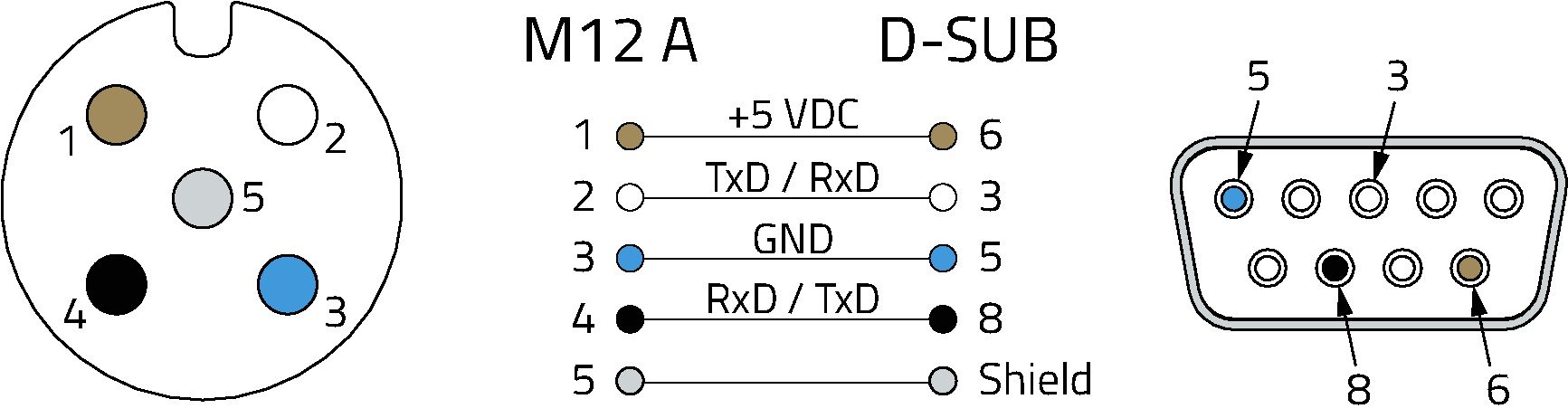
Figure 03. Pin assignment of a five-pin M12-A coded socket for the RS-485 interface.
Profibus enables decentralized concepts. The fact that Profibus can be adapted to different applications using a modular principle also makes this technology attractive in production automation and the process industry. Here the M12 connection technology is indispensable. While the A-coded variants are used for power supply, the B-coded circular connectors are specifically designed for Profibus signal transmission (Figure 4).
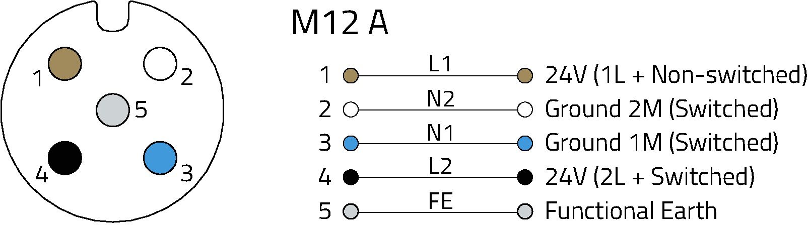
Figure 4. Pin assignment of a 5-pin M12-A coded socket used to power Profibus peripheral devices.
Other industrial bus systems in which the M12-A circular connectors are used are the RS-411, RS-423 and finally the RS-232. Eight-, five- and four-pole connectors are suitable for this. The wiring mainly depends on the required signals, the power supply, and the required earthing.
See this technical article in its entirety or read a version in German.
Visit Würth Elektronik online to learn more about solutions for industrial networks.
Like this article? Check out our other Circular Connectors, Standards and Networking articles, our Industrial Market Page, and our 2023 and 2024 Article Archives.
Subscribe to our weekly e-newsletters, follow us on LinkedIn, Twitter, and Facebook, and check out our eBook archives for more applicable, expert-informed connectivity content.
