Connector Challenges for High-Speed Serial Link Applications
As data rates increase, the bandwidth of signals increases and its rise time decreases. ALL signal integrity problems get worse with higher signal bandwidth and shorter rise time. Here, Dr. Eric Bogatin examines the connector challenges for high-speed serial link applications.
 Thanks in part to Netflix and YouTube, which together comprise as much as 50% of all peak Internet traffic, the electronics industry has “a need for speed.” The doubling in data traffic volume every two years drives higher data transfer rates not only in the backbone, but it also trickles all the way down to the chip level in virtually all systems.
To feed this hungry data monster, every high-speed serial link protocol, like PCIe, SATA, SAS, Ethernet, USB, and Infiniband has a roadmap with a doubling in data rate for each generation. If you were struggling to implement a 2.5Gb/s serial link last year, get ready to implement a 5Gb/s link next year.
One reason designing robust high-data-rate channels is hard is the fundamental properties of electromagnetic signals interacting with conductors and dielectrics. In other words, blame Maxwell’s Equations.
As data rates increase, the bandwidth of signals increases and its rise times decrease. ALL signal integrity problems, unfortunately, get worse with higher signal bandwidth and shorter rise time, especially in structures like connectors, which are inherently non-uniform.
Luckily, connectors are short, so the losses due to converting the propagating electromagnetic fields into heat can be kept very small. But it’s the other three fundamental problems interconnects create which can be much worse in connectors. These problems are reflections from discontinuities, crosstalk from other channels, and mode conversion from asymmetries.
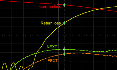
An important metric we use to describe the reflections from discontinuities is how much signal reflects, referred to as the reflection coefficient or the return loss. This is the ratio of the reflected signal to the incident signal, usually expressed in dB. Figure 1 is an example of the return loss, and other S-parameters, for a typical board-to-board connector.

Figure 1. S-parameter performance of a single-ended channel in an “open pin field” board-to-board connector, with some circuit board trace included, courtesy of Samtec’s Solutionator website. The scale is 5 dB per div with 0 dB at the top and 10GHz full scale.
Note that as frequency increases, the return loss increases. How much is too much? When the return loss is more than about -13 dB, the reflected signals start affecting the transmitted signals. This is a common spec used to define the bandwidth of a connector.
Engineering a connector with a higher bandwidth is about more than just the connector. It is also about the board traces leading to it and the pad stack under it. You can’t optimize just the connector, but must include the entire signal path leading to it in the board.
Crosstalk is all about keeping the fringe electric and magnetic fields of one differential pair far away from another differential pair. Unfortunately, the driving force of higher interconnect density moves this problem in exactly the wrong direction.
One solution is to add additional return pins or wide return planes on either side of the signals. The Near End Cross Talk (NEXT) and Far End Cross Talk (FEXT) coefficients are common metrics to describe crosstalk between channels.
The last interconnect pothole to avoid in high-speed serial link applications is mode conversion. We send a differential signal down our channel, but if there is any asymmetry between one line in the differential pair and the other, some of this differential signal will be converted into common signal.
The impact is loss of some differential signal, potentially allowing some of the new common signal to contribute to radiated emissions and allowing the common signal to rattle around the channel, getting converted back into differential signal and looking like noise to the receiver.
The most common asymmetry is a time delay difference between the two lines that make up a channel. At 28Gb/s, for example, the unit interval is only 36 psec. The line-to-line skew for the entire channel should be less than 15% of this, or 5 psec. This is a total channel-length mismatch of no more than 30 mils and only a tiny fraction of this can be allocated to the connector.
But signal integrity is just one of the design constraints. There are also the long-term reliability requirements, the manufacturability, the insertion force, the DC current-carrying capacity, the interconnect density, the profile, and even the board footprint requirements. Usually Murphy’s Law applies and makes connector design a “whack-a-mole” game. Improving a design for one metric makes it worse for another metric.
This complexity has led Dave Dunham, director of signal integrity at Molex, to say, “At 28 Gb/s, everything matters.”
This is why most high-performance connector suppliers must have exceptional signal integrity engineering teams to design their connectors.
In all high-end products, the customers’ circuit boards must be optimized for the specific connector. To stay competitive, connector companies are building their SI expertise not just for their own design challenges but also to assist their customers. This is why Samtec recently acquired Teraspeed Consulting to strengthen its support for solving customers’ SI problems.
At data rates above 5Gb/s, interconnects are not transparent. Achieving an acceptable bit error rate means paying attention to signal integrity right at the beginning.
[hr]
Eric Bogatin is the dean of the new Teledyne LeCroy Signal Integrity Academy, a new web portal for online video SI training. He can be reached at www.beTheSignal.com.


