
Page 7 - ConnectorSupplier.com Mil/Aero Handbook
P. 7
SWaP Management
As with many mil/aero applications, there is a need to manage the SWaP requirements of a connector. Smaller connectors are preferred for high-speed signals, as mentioned above, but larger connectors may be preferred to provide a higher connector current rating. In order to achieve the best of both worlds, hybrid connectors can be implemented. In some high-speed connector designs, 1A nano contacts are used for the high-speed signals, while 3A micro or 5A Size 23 contacts are used for the power pins.
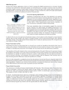
Figure 1: Thorough consideration of design elements including: pin selection, cable selection, SWaP management, pin-to-pin spacing optimization, termination to pins, and shield connections allow Omnetics’ Breakaway USB 3.0 to deliver robust, reliable performance in high-speed mil/aero applications
Pin-to-Pin Spacing Optimization
Impedance is proportional to the ratio of pin diameter to pin spacing. Since connectors with larger pin spacing generally use larger pins, the impedance of most connectors is generally similar, regardless of size. While most high-speed digital applications are based on an impedance of either 90Ω or 100Ω, measurements show that the impedance of most connectors is somewhere between 50Ω and 80Ω.
This lower impedance does not necessarily suggest the connector will fail. However, the signal quality will degrade proportional to the difference between connector impedance and system impedance, and this degradation will occur similarly regardless of whether the connector impedance is too high or too low. Thus, in order for high-speed signals to pass with maximum delity, the impedance through the connector must match the system impedance as closely as possible.
In order for this to occur, the spacing must typically increase or the insulator must be changed to a lower dielectric material. Both of these changes may require a modi ed insulator, but the improved performance often validates this design change. Some high-speed mil/aero designs also increase pin spacing by about 50%, though this can vary based on a range of factors.
Proper Termination to Pins
Terminating the wires of a high-speed pair to connector pins creates an impedance discontinuity that occurs in nearly every connector. This discontinuity can be minimized, but it can rarely be removed. In fact, if great care is not taken in manufacturing, this portion of the design can very easily become the performance bottleneck.
The impedance of the path is based on the cross-sectional geometry of the path. Whenever the geometry changes the impedance will change. In the case of the pin termination, there are three changes to the geometry that cause the impedance to change: the shield is removed for a portion of the twisted pair, the wire spacing increases in order to connect to the pins, or the diameter of the wires is smaller than the diameter of the connector pins. All three of these geometric differences cause the impedance to increase.
Since it is often impossible to completely remove this discontinuity, the next best thing is to keep the length of the discontinuity as small as possible. This is because the length of the discontinuity determines the magnitude of the signal degradation. Engineers can minimize the discontinuity by keeping the twisted pair shield closely wrapped on the differential pair wires and as close as possible to the pin termination.
Proper Shield Connection
The importance of shielding increases proportionately with frequency. This is because higher frequencies have smaller wavelengths, meaning that signals radiate through smaller and smaller holes in the shielding. As a general rule, holes in the shielding should be limited to about 1/200th of a wavelength at the critical frequency. This equates to 0.600” at 1MHz, and 0.060” at 1GHz.
As shown, increased frequencies require an increasingly robust shielding strategy. A basic recommendation is to make sure the shield is terminated on both ends for all signals regardless of frequency. For signals above 100Mbps, a braided shield that is terminated 360° around the connector is recommended. For signals above 1Gbps, an additional foil shield under the braided shield near the connector should be considered in order to minimize any holes that may exist in the shielding. Without proper shielding, signals may radiate to the external world and external signals may interfere with the signals inside the cable assembly.
7
