
Page 21 - ConnectorSupplier.com 2019 How-to-Specify E-Book
P. 21
Vibration and Shock
Because many electronic military and aviation devices are subject to extreme forces of motion, it’s important to understand how a connector handles vibration and shock. Typical problems include:
• Accidental connector disengagement during extreme acceleration or deceleration from excessive gravitational (g) forces.
• Connector or contact disengagement during torsion or flexure of a PCB undergoing roll, pitch, yaw, and other abrupt motions.
• Micro-interruptions of the signal due to wear of contacts by vibrations.
A connector uses mechanically deflected metallic beams arrayed within a shell or housing to form an interface that is separable, yet essentially electrically invisible. Therefore, the first objective of connector design is to maintain the stability of the contact interface against all the factors that could cause signal or power loss.
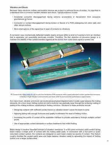
TE Connectivity’s MULTIGIG RT 2-R is a pin-less backplane PCB connector with a quad-redundant contact system that increases reliability in high-vibration environments and meets VITA 72 environmental performance requirements.
At a macro level, vibration and shock can involve gross physical displacement or create a gap between the mating elements. At a micro level, fretting motion (or micro-motions) can gradually wear through the surfacing coating or plating of the mating surfaces, contributing to fretting corrosion. Solutions to these problems include:
• Designing contacts with sufficient contact forces so vibration doesn’t cause the beam to jump.
• Applying plating with enough thickness and quality to withstand the wear of fretting motion.
• Increasing the points of contact at the separable interface to provide redundancy through multiple contact points.
• Use of appropriate contact lubricants or surface treatments that inhibit fretting.
Beam design is another important element of vibration resistance. In a two-point connector, each contact spring beam makes a single point of contact with the mating wafer pads. In connectors with a four-point or quad- redundant contact system, the contacts are designed so each beam makes two points of contact. This feature roughly doubles the contact patch area and helps balance vibration loads by spreading the impact of fretting motion over a larger surface area.
21
